
Page 390 - Programmable Logic Controllers, Fifth Edition
P. 390
• When the sixth part arrives the Container_Counter_
Counts counter will then be done, thereby allow- the same as those associated with the CTU function block.
The CTD instruction is typically used with a CTU instruc-
ing the solenoid to actuate for any container after tion that references the same counter structure.
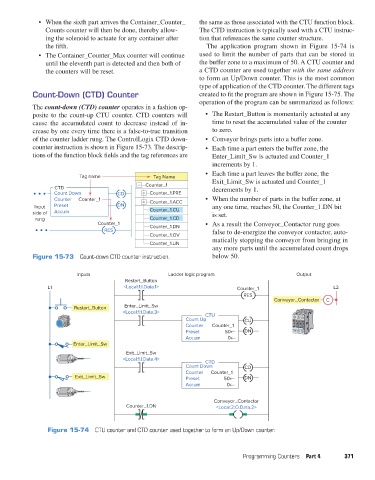
the fifth. The application program shown in Figure 15-74 is
• The Container_Counter_Max counter will continue used to limit the number of parts that can be stored in
until the eleventh part is detected and then both of the buffer zone to a maximum of 50. A CTU counter and
the counters will be reset. a CTD counter are used together with the same address
to form an Up/Down counter. This is the most common
type of application of the CTD counter. The different tags
Count-Down (CTD) Counter created to fit the program are shown in Figure 15-75. The
operation of the program can be summarized as follows:
The count-down (CTD) counter operates in a fashion op-
posite to the count-up CTU counter. CTD counters will • The Restart_Button is momentarily actuated at any
cause the accumulated count to decrease instead of in- time to reset the accumulated value of the counter
crease by one every time there is a false-to-true transition to zero.
of the counter ladder rung. The ControlLogix CTD down- • Conveyor brings parts into a buffer zone.
counter instruction is shown in Figure 15-73. The descrip- • Each time a part enters the buffer zone, the
tions of the function block fields and the tag references are Enter_Limit_Sw is actuated and Counter_1
increments by 1.
• Each time a part leaves the buffer zone, the
Tag name Tag Name
Counter_1 Exit_Limit_Sw is actuated and Counter_1
CTD decrements by 1.
Count Down CD Counter_1.PRE
Counter Counter_1 Counter_1.ACC • When the number of parts in the buffer zone, at
Input Preset DN any one time, reaches 50, the Counter_1.DN bit
side of Accum Counter_1.CU is set.
rung Counter_1.CD
Counter_1 Counter_1.DN • As a result the Conveyor_Contactor rung goes
RES false to de-energize the conveyor contactor, auto-
Counter_1.OV
matically stopping the conveyor from bringing in
Counter_1.UN
any more parts until the accumulated count drops
Figure 15-73 Count-down CTD counter instruction. below 50.
Inputs Ladder logic program Output
Restart_Button
L1 <Local:1:I.Data.1> Counter_1 L2
RES
Conveyor_Contactor C
Restart_Button Enter_Limit_Sw
<Local:1:I.Data.3> CTU
Count Up CU
Counter Counter_1
Preset DN
Accum
Enter_Limit_Sw
Exit_Limit_Sw
<Local:1:I.Data.4> CTD
Count Down CD
Counter Counter_1
Exit_Limit_Sw Preset DN
Accum
Conveyor_Contactor
Counter_1.DN <Local:2:O.Data.2>
Figure 15-74 CTU counter and CTD counter used together to form an Up/Down counter.
Programming Counters Part 4 371
pet73842_ch15_333-394.indd 371 03/11/15 7:34 PM