
Page 398 - Programmable Logic Controllers, Fifth Edition
P. 398
L1
Inputs
Count_PB Ladder Logic program
<Local:1:I.Data.1>
CTU
Count Up CU
Count_PB Outputs L2
Counter C1
Preset 25 DN
Accum 0 PL_1
PL_1
Reset_PB GRT LES <Local:2:O.Data.1> PL_2
Greater Than (A>B) Less Than (A<B)
Source A C1.ACC Source A C1.ACC
0 0 PL_3
Source B 5 Source B 10
PL_2
EQU <Local:2:O.Data.2>
Equal
Source A C1.ACC
0
Source B 15
PL_3
NEQ <Local:2:O.Data.3>
Not Equal
Source A C1.ACC
0
Source B 20
C1.DN C1
RES
Reset_PB
<Local:1:I.Data.2>
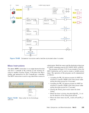
Figure 15-89 Comparison instructions used to test the accumulated value of a counter.
Move Instructions a destination. Both the source and the destination data type
of a MOV instruction may be INT, DINT, SINT, or REAL.
The move (MOV) instruction is an output instruction that The program of Figure 15-91 is an example of how the
can move a constant or the contents of one memory lo- MOV instruction can be used to create a variable preset
cation to another location. Figure 15-90 shows the Move timer. The operation of the program can be summarized
toolbar and instruction for the ControlLogix controller. as follows:
The MOV instruction is used to copy data from a source to
• Actuating the PB_10s button executes its MOV in-
struction to transfer 10000 to the timer preset value
setting the delay period for 10 seconds.
• Actuating the PB_15s button executes its MOV in-
MOV MVM AND OR XOR SWPB NOT CLR BTD
struction to transfer 15000 to the timer preset value
Move/Logical
setting the delay period for 15 seconds.
MOV • Closing the Timer_Start switch starts the timer
Move timing.
Source
• While the timer is timing, the pilot light PL_1 is on
Dest for the duration of the timer preset period.
Figure 15-90 Move toolbar for the ControlLogix • When the timer times out, PL_1 turns off and PL_2
controller. turns on.
Math, Comparison, and Move Instructions Part 5 379
pet73842_ch15_333-394.indd 379 03/11/15 7:34 PM