
Page 43 - Programmable Logic Controllers, Fifth Edition
P. 43
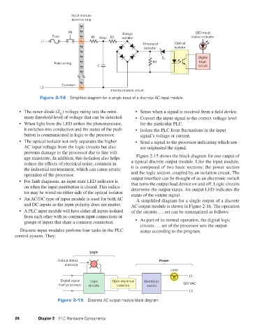
Input module
                                          terminal strip
                                        PB                       Bridge                            LED input
                                 Fuse              R1  Filter R2   rectifier                      status indicator
                            L1
                                                                           Threshold      Optical
                                                                           detector       isolator

                                                                                                     Digital
                                                                                    Z D
                                  Field wiring                                 R3                    logic
                                                      C                                              circuit


                                     Common
                           L2
                                                            Internal module circuit
                           Figure 2-14  Simplified diagram for a single input of a discrete AC input module.


                 •  The zener diode (Z ) voltage rating sets the mini-  •  Sense when a signal is received from a field device.
                                    D
                    mum threshold level of voltage that can be detected.  •  Convert the input signal to the correct voltage level
                 •  When light from the LED strikes the phototransistor,   for the particular PLC.
                    it switches into conduction and the status of the push-  •  Isolate the PLC from fluctuations in the input
                    button is communicated in logic to the processor.     signal’s voltage or current.
                 •  The optical isolator not only separates the higher   •  Send a signal to the processor indicating which sen-
                    AC input voltage from the logic circuits but also     sor originated the signal.
                    prevents damage to the processor due to line volt-
                    age transients. In addition, this isolation also helps   Figure 2-15 shows the block diagram for one output of
                    reduce the effects of electrical noise, common in   a typical discrete output module. Like the input module,
                    the industrial environment, which can cause erratic   it is composed of two basic sections: the power section
                    operation of the processor.                      and the logic section, coupled by an isolation circuit. The
                 •  For fault diagnosis, an input state LED indicator is   output interface can be thought of as an electronic switch
                    on when the input pushbutton is closed. This indica-  that turns the output load device on and off. Logic circuits
                    tor may be wired on either side of the optical isolator.  determine the output status. An output LED indicates the
                                                                     status of the output signal.
                 •  An AC/DC type of input module is used for both AC   A simplified diagram for a single output of a discrete
                    and DC inputs as the input polarity does not matter.  AC output module is shown in Figure 2-16. The operation
                 •  A PLC input module will have either all inputs isolated   of the circuits . . . .set can be summarized as follows:
                    from each other with no common input connections or
                    groups of inputs that share a common connection.   •  As part of its normal operation, the digital logic
                                                                          circuits . . . .set of the processor sets the output
                  Discrete input modules perform four tasks in the PLC    status according to the program.
               control system. They:


                                                  Logic
                                   Output status                                   Power
                                       indicator
                                                                                        Load
                                                                                                L1
                                     Digital signal  Logic   Opto-electrical  Electronic
                                    from processor  circuits   isolation     switch           120 VAC
                                                                                                L2
                                   Figure 2-15  Discrete AC output module block diagram.


               24         Chapter 2  PLC Hardware Components


          pet73842_ch02_017-045.indd   24                                                                               03/11/15   3:43 PM