
Page 127 - Programmable Logic Controllers, Fifth Edition - Mobile version
P. 127
Receiver
long-range sensing. Quite often, a garage door opener has
Load in only one direction, through-beam scanning provides
Modulated a through-beam photoelectric sensor mounted near the
light
beam floor, across the width of the door. For this application
the sensor senses that nothing is in the path of the door
when it is closing.
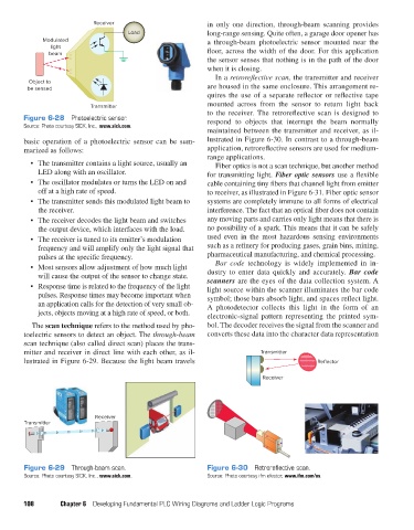
In a retroreflective scan, the transmitter and receiver
Object to
be sensed are housed in the same enclosure. This arrangement re-
quires the use of a separate reflector or reflective tape
Transmitter mounted across from the sensor to return light back
to the receiver. The retroreflective scan is designed to
Figure 6-28 Photoelectric sensor. respond to objects that interrupt the beam normally
Source: Photo courtesy SICK, Inc., www.sick.com.
maintained between the transmitter and receiver, as il-
basic operation of a photoelectric sensor can be sum- lustrated in Figure 6-30. In contrast to a through-beam
marized as follows: application, retroreflective sensors are used for medium-
range applications.
• The transmitter contains a light source, usually an Fiber optics is not a scan technique, but another method
LED along with an oscillator. for transmitting light. Fiber optic sensors use a flexible
• The oscillator modulates or turns the LED on and cable containing tiny fibers that channel light from emitter
off at a high rate of speed. to receiver, as illustrated in Figure 6-31. Fiber optic sensor
• The transmitter sends this modulated light beam to systems are completely immune to all forms of electrical
the receiver. interference. The fact that an optical fiber does not contain
• The receiver decodes the light beam and switches any moving parts and carries only light means that there is
the output device, which interfaces with the load. no possibility of a spark. This means that it can be safely
• The receiver is tuned to its emitter’s modulation used even in the most hazardous sensing environments
frequency and will amplify only the light signal that such as a refinery for producing gases, grain bins, mining,
pulses at the specific frequency. pharmaceutical manufacturing, and chemical processing.
• Most sensors allow adjustment of how much light Bar code technology is widely implemented in in-
will cause the output of the sensor to change state. dustry to enter data quickly and accurately. Bar code
scanners are the eyes of the data collection system. A
• Response time is related to the frequency of the light light source within the scanner illuminates the bar code
pulses. Response times may become important when symbol; those bars absorb light, and spaces reflect light.
an application calls for the detection of very small ob- A photodetector collects this light in the form of an
jects, objects moving at a high rate of speed, or both. electronic-signal pattern representing the printed sym-
The scan technique refers to the method used by pho- bol. The decoder receives the signal from the scanner and
toelectric sensors to detect an object. The through-beam converts these data into the character data representation
scan technique (also called direct scan) places the trans-
mitter and receiver in direct line with each other, as il- Transmitter
lustrated in Figure 6-29. Because the light beam travels Reflector
Receiver
Receiver
Transmitter
Figure 6-29 Through-beam scan. Figure 6-30 Retroreflective scan.
Source: Photo courtesy SICK, Inc., www.sick.com. Source: Photo courtesy ifm efector, www.ifm.com/us.
108 Chapter 6 Developing Fundamental PLC Wiring Diagrams and Ladder Logic Programs
pet73842_ch06_098-130.indd 108 05/11/15 4:20 PM