
Page 59 - Programmable Logic Controllers, Fifth Edition - Mobile version
P. 59
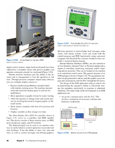
Figure 2-51  Allen-Bradley Pico GFX-70 controller.
                                                                     Source: Image Courtesy of Rockwell Automation, Inc.

                                                                     allowing operators to acknowledge fault messages, enter
                                                                     values,  and  initiate actions.  Users  can  create  both  the
                                                                     control program and HMI functionality using a personal
                                                                     computer with PicoSoft Pro software installed or the con-
               Figure 2-50  Human Machine Interface (HMI).           troller’s on-board display buttons.
               Source: Courtesy of Nercon.
                                                                        Human Machine Interfaces (HMIs), are also referred to
                                                                     as User Interface, Operator Panel, or Terminal and provide a
               digital control systems, larger hard-wired panels have been   means of controlling, monitoring, managing, and/or visual-
               replaced by a computer screen with process graphics and   izing device processes. They can be located on the machine
               operator commands entered via a keyboard (Figure 2-50).   or in centralized control rooms. The general structure of an
                  Human machine interfaces give the ability to the op-  HMI package is shown in Figure 2-52. The tag database vari-
               erator and to management to view the operation in real   ables are programmed to interact with the graphic screen ob-
               time. Through personal computer–based setup software,   jects and communicate with the PLC through the I/O server.
               you can configure display screens to:
                                                                        The design of the HMI application plays a critical role
                 •  Replace hardwired pushbuttons and pilot lights   in determining the operator’s ability to effectively man-
                    with realistic-looking icons. The machine operator   age the operation, particularly in response to abnormal
                    need only touch the display panel to activate the   situations. The major tasks in the development of an HMI
                    pushbuttons.                                     application are:
                 •  Show operations in graphic format for easier viewing.  •  Set up the communication with the PLC. This
                 •  Allow the operator to change timer and counter pre-   involves configuring all necessary software and
                    sets by touching the numeric keypad graphic on the    hardware components.
                    touch screen.
                 •  Show alarms, complete with time of occurrence and            HMI Package                PLC
                    location.                                             Tag Database
                 •  Display variables as they change over time.
                                                                                          I/O
                  The Allen-Bradley Pico GFX-70 controller, shown in                     Server
               Figure  2-51, serves as a controller with HMI capabili-
               ties. This device consists of three modular parts: an HMI,                          Communication
                 processor/power supply, and I/O modules.                                              ports
                  The display/keypad can be used as an operator inter-      Start  Stop  Graphic
                                                                                     Screen
               face or can be linked to control operations to provide real-
               time feedback. It has the ability to show text, date and
               time, as well as custom messages and bitmap graphics,   Figure 2-52  General structure of a HMI package.


               40         Chapter 2  PLC Hardware Components


          pet73842_ch02_017-045.indd   40                                                                               03/11/15   3:44 PM