
Page 172 - Servo Motors and Industrial Control Theory
P. 172
168 Appendix A
function. Determine the natural frequency, damping ratio, and the gain. Show
the transfer function in block diagram form.
40 0
32 –18
–36
24
amplitude ratio (db) M(ω) –16 8 0 phase lag ψ(ω) –108
16
–54
–72
–90
–8
–126
–24
–32
–162
–40 –144
–180
1 10 100 1•10 3 1•10 4 1 10 100 1•10 3 1•10 4
ω ω
frequency (rad/sec) frequency (rad/sec)
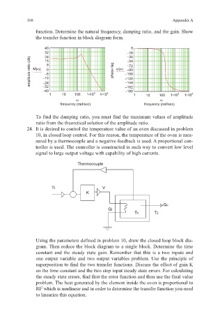
To find the damping ratio, you must find the maximum values of amplitude
ratio from the theoretical solution of the amplitude ratio.
24. It is desired to control the temperature value of an oven discussed in problem
10, in closed loop control. For this reason, the temperature of the oven is mea-
sured by a thermocouple and a negative feedback is used. A proportional con-
troller is used. The controller is constructed in such way to convert low level
signal to large output voltage with capability of high currents.
Thermocouple
Ti V
K
Qo
Qi
To T2
Using the parameters defined in problem 10, draw the closed loop block dia-
gram. Then reduce the block diagram to a single block. Determine the time
constant and the steady state gain. Remember that this is a two inputs and
one output variable and two output variables problem. Use the principle of
superposition to find the two transfer functions. Discuss the effect of gain K
on the time constant and the two step input steady state errors. For calculating
the steady state errors, find first the error function and then use the final value
problem. The heat generated by the element inside the oven is proportional to
2
RI which is nonlinear and in order to determine the transfer function you need
to linearize this equation.