
Page 229 - Servo Motors and Industrial Control Theory
P. 229
Appendix C 227
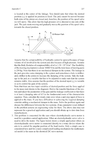
is located at the center of the linkage. You should note that when the desired
position ( y ) is applied its position is fixed. The jack cannot be moved because
i
both sides of the piston are closed and, therefore, the position of the spool valve
(x) will move. This allow that the high pressure oil is directed to one side of the
jack. The jack starts moving and gradually moves the position of the spool valve
towards the closed position.
P s
Oil Return Path
x
Y i
K s
Y 0 M
Assume that the compressibility of hydraulic cannot be ignored because of large
volume of oil involved in the system and also because of high pressure. Assume
that the Bulk Modulus of compressibility of oil is 1.38 × 10 N/m . The flexibility
9
2
of the moving mechanism is about 10000 N/m and the total mass of moving parts
is 250 kg. Note that there is no mechanical damper in the system. The leakage in
the jack provides some damping in the system and sometimes a hole is deliber-
ately drilled in the piston to increase the damping of the system. Take the leak-
age in the jack as a variable that has to be adjusted to make sure that the system
remains stable. Also assume that the position of the desired input ( y ) is variable
i
so as to control the gain of the system.
Note that there are two input variables of desired position and the force applied
to the mass (not shown in the diagram). Derive the transfer functions of the sys-
tem and adjust the parameters of the gain and the leakage coefficient so that there
is at least a damping ratio of 0.5 in the fundamental roots of the characteristic
equation. Then, calculate the steady state error when a unit step input of force is
applied to the mass. If you have difficulties in achieving the required damping
consider adding a mechanical damper to the mass. Solve the problem again and
discuss the differences between the two systems. If any parameter is not defined
in the problem assume an engineering value for them. The above data may not
represent for a practical application and you should obtain up to date data from
manufacturers.
3. This problem is concerned for the case where electrohydraulic servo motor is
used for a position control application. Often an electrohydraulic servo valve is
used to drive the motor. The figure below shows a simple application where an
electrohydraulic servo motor is connected directly to a rotary device where the
aim is to control the angular position of the load inertia. Only a simple case is
considered here and for a more complicated loading mechanism the mathemati-
cal model is the same as the electrical DC servo motors.