
Page 479 - Mechatronics with Experiments
P. 479
October 9, 2014 8:41 254mm×178mm
Printer: Yet to Come
JWST499-c07
JWST499-Cetinkunt
ELECTROHYDRAULIC MOTION CONTROL SYSTEMS 465
Pilot
supply Tank
Valve
actuator Pilot valve
force
Control
chamber
Valve
body
Poppet
P
2
Main outport
Seat
Main inport
P
1
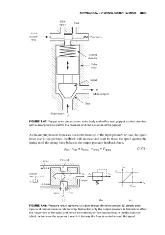
FIGURE 7.47: Poppet valve construction: valve body and orifice seat, poppet, control chamber
with a mechanism to control the pressure or direct actuation of the poppet.
As the output pressure increases due to the increase in the input pressure or load, the spool
force due to the pressure feedback will increase and start to move the spool against the
spring until the spring force balances the output pressure feedback force,
p out ⋅ A out ≈ k spring ⋅ x spring = F spring (7.171)
Flow path
Spring
P
out
P
Leakage x P out P in P out out, max
drain
Aout
Outport
T P
in
P
in, max
x
Inport max
P
in
(a) (b) (c)
FIGURE 7.48: Pressure reducing valve: (a) valve design, (b) valve symbol, (c) steady-state
input and output pressure relationship. Notice that only the output pressure is fed back to affect
the movement of the spool and hence the metering orifice. Input pressure ideally does not
affect the force on the spool as a result of the way the flow is routed around the spool.