Page 487 - Mechatronics with Experiments
P. 487

Printer: Yet to Come
                                                                                     October 9, 2014 8:41 254mm×178mm
                        JWST499-Cetinkunt
            JWST499-c07
                                                            ELECTROHYDRAULIC MOTION CONTROL SYSTEMS  473
                                 Pre-compensator
                                   valve
                                                                                    P
                                                             A 1                       P
                                           Adjustable                                   s
                                            orifice                                    P
                                                                                        f b1
                             P s                         P s                           P      Δ p ~ k spring
                                                                                        f b2
                                                                    P
                                       P                            f b1
                                        f b1  Δ  p  P f b2       A 2
                                                         k spring            P f b2
                                         (a)                       (b)                   (c)
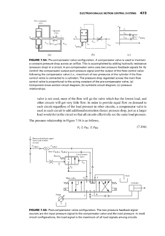
                             FIGURE 7.54: Pre-compensator valve configuration. A compensator valve is used to maintain
                             a constant pressure drop across an orifice. This is accomplished by adding hydraulic resistance
                             (pressure drop) in a circuit. A pre-compensator valve uses two pressure feedback signals for its
                             control: the compensator output port pressure signal and the output of the flow control valve
                             following the compensator valve (i.e., maximum of two pressures of the cylinder if the flow
                             control valve is connected to a cylinder). The pressure drop regulated across the main flow
                             control valve is proportional to the spring constant of the pre-compensator valve. (a)
                             Component cross-section circuit diagram, (b) symbolic circuit diagram, (c) pressure
                             relationships.


                                  valve is not used, most of the flow will go the valve which has the lowest load, and
                                  other circuits will get very little flow. In order to provide equal flow on demand to
                                  each circuit regardless of the load pressure in other circuits, a compensator valve is
                                  used in each circuit to add additional restriction (hence pressure drop, just as a larger
                                  load would do) in the circuit so that all circuits effectively see the same load pressure.
                             The pressure relationship in Figure 7.54 is as follows,
                                                           p ≥ p fb1  ≥ p fb2                  (7.194)
                                                            s


                               Pressure feedback signal
                               from load of other
                               circuits
                               P A/B,2    P A/B,1
                                         max (P A/B,1 , P A/B,2 )
                                                          Compensator
                                             Kspring        valve
                                                              P
                                               P              S
                                                l
                                                      P
                                                       S
                                                                                        Tank
                                                    Main valve  P S    T
                                                                                            Cylinder


                                              Pump             P    A  B


                             FIGURE 7.55: Post-compensator valve configuration. The two pressure feedback signal
                             sources are the input pressure signal to the compensator valve and the load pressure. In multi
                             circuit configurations, the load signal is the maximum of all load signals among circuits.
   482   483   484   485   486   487   488   489   490   491   492