
Page 565 - Mechatronics with Experiments
P. 565
October 9, 2014 8:41 254mm×178mm
Printer: Yet to Come
JWST499-c07
JWST499-Cetinkunt
ELECTROHYDRAULIC MOTION CONTROL SYSTEMS 551
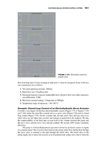
Solenoid current
100
50
0
Poppet position
0.2
0.15
0.1
0.05
0
P2 and PS
3000
2000
1000
0
Q2 and Q4
6
4
2
0
0 1 2 3 4 5 FIGURE 7.101: Simulation result of a
Time (s) poppet valve.
flow from load (port 2) back to pump or tank (port 1) when de-energized. Some of the key
valve parameters are as follows
1. The rated operating pressure: 3000 psi
2. Rated flow rate: 5.8 gallons∕min
3. Estimated transient response (bandwidth) from current to flow rate under rated pres-
sure differential: 10 Hz.
4. Maximum internal leakage: 5 drops∕min at 3000 psi
◦
5. Temperature range of operation: −40–100 C
Example: Closed Loop Control of an Electrohydraulic Servo Actuator
Consider a one degree of freedom electrohydraulic system (Figure 7.75 or Figures 7.103
and 7.104) where the main flow control valve is a servo valve (Figure 7.60) and its closed
loop control (Figure 7.76). On the cylinder side, the line relief valve and line cross-over
relief valves are not taken into account, and leakage is neglected in the analysis. We take
the compressibility of the fluid into account both in the volume between the pump and
the servo valve, and the servo valve and the cylinder. We assume 100% pump volumetric
efficiency.
The pump is of fixed displacement type and is driven by an electric motor or engine
at a constant speed. The excessive flow between the pump output flow and the flow through
the servo valve is returned to the tank through the relief valve. The relief valve on the
pump supply line is taken into account as an instantaneously acting valve; that is when the