Page 596 - Mechatronics with Experiments
P. 596

JWST499-Cetinkunt
            JWST499-c07
                       582   MECHATRONICS  Printer: Yet to Come                      October 9, 2014 8:41 254mm×178mm
                              These specifications (rated flow rate and rated pressure) then determine the size of the
                              flushing valves, charge pump, and valves in the circuit.
                                   One of the important engineering constraints is the maximum line pressure in the
                              hydraulic lines, which sets the relief valve pressure settings,
                                                        p relief  = p l,max  ≈ 50 MPa           (7.750)
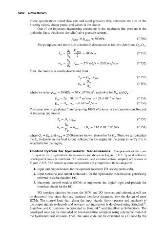
                                   The pump size and motor size selection is determined as follows: determine D , D .
                                                                                                 p
                                                                                                    m
                                                     R f  F l,max
                                                T =     ⋅     = 500 Nm                          (7.751)
                                                 m
                                                     N g   2
                                                     N g
                                               w =      ⋅ V max  = 277 rad∕s = 2652 rev∕min     (7.752)
                                                 m
                                                     R f
                              Then, the motor size can be determined from
                                                            T = D ⋅ p                           (7.753)
                                                             m    m   line
                                                                 Q m
                                                           w =                                  (7.754)
                                                             m
                                                                 D m
                                                                6
                                                                     2
                              where we select p line  = 50 MPa = 50 × 10 N∕m , and solve for D and Q .
                                                                                   m
                                                                                         m
                                                                                  3
                                                               3
                                             D = 2   ⋅ 10 ⋅ 10 −6  m ∕rev = 6.28 × 10 −5  m ∕rev  (7.755)
                                               m
                                                                  3
                                             Q = D ⋅ w = 0.167 m ∕min                           (7.756)
                                               m    m   m
                              The pump size is calculated from (assuming 100% efficiency in the transmissions line and
                              at the pump and motor)
                                               T = D ⋅ p line                                   (7.757)
                                                p
                                                     p
                                                    Q p
                                                                                3
                                               w =     = w   ⟶ D = 6.65 × 10 −5  m ∕rev         (7.758)
                                                p         eng     p
                                                   D
                                                     p
                              where Q = Q and w eng  = 2500 rpm are known, then solve for D . Then, we can calculate
                                                                                  p
                                         m
                                     p
                              the T to determine the load torque reflected on the engine by the pump to verify if it is
                                  p
                              acceptable for the engine.
                              Control System for Hydrostatic Transmissions        Components of the con-
                              trol system for a hydrostatic transmission are shown in Figure 7.112. Typical software
                              development tools (a notebook PC, software, and communication adaptor) are shown in
                              Figure 7.113. The control system components are grouped into three categories:
                                1. input and output devices for the operator (operator I/O devices in the cab),
                                2. input (sensors) and output (solenoids) for the hydrostatic transmission, generically
                                   referred to as the machine I/O,
                                3. electronic control module (ECM) to implement the digital logic and provide the
                                   interface circuit for the I/O.
                                   I/O interface circuitry between the ECM and I/O (sensors and solenoids) will not
                              be discussed here since they are standard interfaces integrated into the design of most
                              ECMs. The control logic that relates the input signals (from operator and machine) to
                                                                                                    ®
                              the output signals (solenoids and operator cab indicators) is developed using Simulink ,
                              Stateflow, and C-functions incorporated to Simulink ®  and Stateflow as S-functions. The
                              developed code can be simulated on a non-real-time computer using a dynamic model of
                              the hydrostatic transmission. Then, the same code can be converted to a C-code by the
   591   592   593   594   595   596   597   598   599   600   601