
Page 786 - Mechatronics with Experiments
P. 786
772 MECHATRONICS
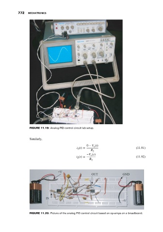
FIGURE 11.19: Analog PID control circuit lab setup.
Similarly,
0 − V (t)
o
i (t) = (11.91)
2
R 2
−V (s)
o
i (s) = (11.92)
2
R
2
FIGURE 11.20: Picture of the analog PID control circuit based on op-amps on a breadboard.