
Page 794 - Mechatronics with Experiments
P. 794
780 MECHATRONICS
input pin status would be low (OFF). This is called the pull-up resistor configuration,
because the resistor “pulls-up” the pin to the supply voltage.
4. Open MPLAB environment, and load your project or open a new project. Your code
for the project must contain two separate sections as described earlier: a setup section
and logic section.
5. Polling method of programming: the logic implemented between the input DIP
switches and output LEDs is left to the student. One simple logic implementation
may be to display the same state of DIP switches on the LEDs.
6. Implement an interrupt driven program using a timer: use one of the timers modules
(i.e., TIMER0, TIMER1, TIMER2) to generate an interrupt at a programmed fre-
quency. Write the interrupt service routine (ISR) for the timer interrupt which will
read the input switches, and write the status of the inputs to the output LEDs. Setup
the priority of the interrupt. Direct the timer interrupt to the written ISR function.
7. Implement an interrupt driven program based on an external event (instead of a timer):
a change of state in any of the input switches is defined as the interrupt. Perform the
same function.
11.8 EXPERIMENT 8: FORCE AND STRAIN MEASUREMENT
USING A STRAIN GAUGE AND PIC-ADC INTERFACE
Objectives
1. Build a complete circuit to interface a strain-gauge sensor to the A/D converter of the
PIC microcontroller. This includes building a Wheatstone bridge and an operational
amplifier to amplify the voltage output of the Wheatstone bridge, and interfacing it
to one of the ADC channels of the PIC controller.
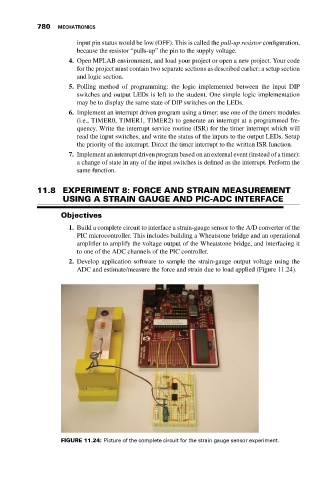
2. Develop application software to sample the strain-gauge output voltage using the
ADC and estimate/measure the force and strain due to load applied (Figure 11.24).
FIGURE 11.24: Picture of the complete circuit for the strain gauge sensor experiment.