
Page 89 - Mechatronics with Experiments
P. 89
CLOSED LOOP CONTROL 75
r(.) y(.)
_ D(.) G(.)
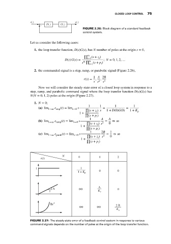
FIGURE 2.26: Block diagram of a standard feedback
control system.
Let us consider the following cases:
1. the loop transfer function, D(s)G(s), has N number of poles at the origin s = 0,
∏ m
i
i=1 (s + z )
D(s) G(s) = ∏ n ; N = 0, 1, 2, ....
s N (s + p )
i=1 i
2. the commanded signal is a step, ramp, or parabolic signal (Figure 2.26),
1 A 2B
r(s) = , ,
s s 2 s 3
Now we will consider the steady-state error of a closed loop system in response to a
step, ramp, and parabolic command signal where the loop transfer function D(s)G(s) has
N(N = 0, 1, 2) poles at the origin (Figure 2.27).
1. N = 0;
1 1 1 1
(a) lim e (t) = lim s = =
t→∞ step s→0 ∏
(s + z ) s 1 + D(0)G(0) 1 + K p
i
1 + ∏
(s + p )
i
1 A A
e
(b) lim t→∞ ramp (t) = lim s→0 s ∏ = ⇒ ∞
(s + z ) s 2 0
i
1 + ∏
(s + p )
i
1 2B 1
e
(c) lim t→∞ parab (t) = lim s→0 s ∏ = ⇒ ∞
(s + z ) s 3 0
i
1 + ∏
(s + p )
i
N
r(t) 0 1 2
1 1
1 + K p 0 0
A ∞ A 0
1 K v
Bt 2
∞ ∞ 2 B
K a
FIGURE 2.27: The steady-state error of a feedback control system in response to various
command signals depends on the number of poles at the origin of the loop transfer function.