
Page 265 - From GMS to LTE
P. 265
Long Term Evolution (LTE) and LTE-Advanced Pro 251
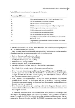
Table 4.6 Downlink control channel message types (DCI formats).
Message type (DCI format) Content
0 Uplink scheduling grants for the PUSCH (see Section 4.5.2)
1 PDSCH assignments with a single codeword
1a PDSCH compact downlink assignment
1b PDSCH compact downlink assignment with precoding vector
1c PDSCH assignments using a very compact format
1d PDSCH assignments for multiuser MIMO
2 PDSCH assignments for closed‐loop MIMO
2a PDSCH assignments for open‐loop MIMO
3 Transmit power control for the UL with 2‐bit power adjustments
(see Section 4.5.2)
3a Transmit power control for the UL with 1‐bit power adjustments
(see Section 4.5.2)
Control Information (DCI) format. Table 4.6 shows the 10 different message types or
DCI formats that have been defined.
If the message describes a downlink assignment for a mobile device on the downlink
shared channel, the message contains the following information:
the type of resource allocation (see below);
●
a power control command for the PUCCH;
●
HARQ information (new data bit, RV);
●
modulation and coding scheme;
●
number of spatial layers for MIMO operation;
●
precoding information (how to prepare the data for transmission).
●
The eNode‐B has several ways to indicate a resource allocation:
Type 0 resource allocations give a bitmap of assigned RB groups. For 10 MHz chan-
●
nels, the group size is three RBs. For the 50 RBs of a 10 MHz channel, the bitmap has
a length of 17 bits. For 20 MHz carriers, a group size of four RBs is used and the 100
RBs are addressed with a bitmap of 25 bits.
Type 1 resource allocations also use a bitmap, but instead of assigning full groups to
●
a mobile device with a ‘1’ in the bitmap, only one of the RBs of a group is assigned.
This way, resource assignments can be spread over the complete band and frequency
diversity can thus be exploited.
Type 2 resource allocations give a starting point in the frequency domain and the
●
number of allocated resources. The resources can either be continuous or spread over
the complete channel.
In summary, the allocation of downlink resources from the mobile device’s point of
view works as shown in Figure 4.16. At the beginning of each subframe, the mobile
device first reads the PCFICH to detect the number of columns of the subframe that are
reserved for the control region in which the PDCCH messages are sent. On the basis of