
Page 271 - From GMS to LTE
P. 271
Long Term Evolution (LTE) and LTE-Advanced Pro 257
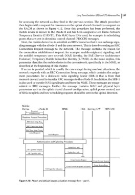
for accessing the network as described in the previous section. The attach procedure
then begins with a request for resources on the uplink shared channel via a request on
the RACH as shown in Figure 4.12. Once this procedure has been performed, the
mobile device is known to the eNode‐B and has been assigned a Cell Radio Network
Temporary Identity (C‐RNTI). This MAC‐layer ID is used, for example, in scheduling
grants that are sent in downlink control channel (PDCCH) messages.
Next, the mobile device has to establish an RRC channel so that it can exchange sign-
aling messages with the eNode‐B and the core network. This is done by sending an RRC
Connection Request message to the network. The message contains the reason for
the connection establishment request, for example, mobile‐originated signaling, and
the mobile’s temporary core network (NAS) identity, the SAE (Service Architecture
Evolution) Temporary Mobile Subscriber Identity (S‐TMSI). As the name implies, this
parameter identifies the mobile device in the core network, specifically in the MME, as
described at the beginning of this chapter.
If access is granted, which is usually the case except during overload situations, the
network responds with an RRC Connection Setup message, which contains the assign-
ment parameters for a dedicated radio signaling bearer (SRB‐1) that is from that
moment onward used to transfer RRC messages to the eNode‐B. In addition, the SRB‐1
is also used to transfer NAS signaling to and from the MME. These messages are encap-
sulated in RRC messages. Further, the message contains MAC and physical layer
parameters such as the uplink shared channel configuration, uplink power control, use
of SRSs in uplink and how scheduling requests should be sent in the uplink direction.
Mobile
Device eNode-B MME HSS Serving-GW PDN-GW
Broadcast
to find network
Random Access Procedure
RRC Con. Setup Req.
RRC Connection Setup
RRC Con. Setup Compl.
(Attach Request)
Attach Request
Authentication and Ciphering Procedure
Update Loc. Req.
UE Capability Enquiry
Update Loc. Ack.
UE Capability Info.
Create Session Request
Create Session Request
Create Session Resp.
Create Session Response (accepted)
UE Capability Indication
Figure 4.18 Attach and default bearer activation message flow – part 1.