
Page 423 - From GMS to LTE
P. 423
Wireless Local Area Network (WLAN) 409
devices attempt to send data waiting in their output queue at the same time. The device
with the smallest backup time will send its data first. All other devices will see the trans-
mission, stop their backup timer and repeat the procedure once the transmission is
over. In spite of this procedure if two devices still attempt to send packets at the same
time, the transmissions will interfere with each other and thus no ACK frame will be
sent. Both stations then have to retransmit their packets. If a collision occurs, the maxi-
mum possible backup time from which the random generator can choose is increased
in the affected devices. This ensures that even in a high‐load situation the number of
collisions remains small.
The backoff time is divided into slots of 20 microseconds. For the first transmission
attempts, the random generator will select 1 of the 31 possible slots. If the transmission
fails, the window size is increased to 63 slots, then to 127 slots and so on. The maximum
window size is 1023 slots, which equals 20 milliseconds. In the 802.11n standard, the
first backoff window has been reduced to 15 slots, that is, 0.3 milliseconds.
In addition to the detection of an ongoing transmission and the use of a backoff
time, each packet header contains an NAV field to inform the other devices of the
time required to send the current frame and the following ACK frame. This addi-
tional feature is especially useful if the air interface is reserved via RTS and CTS
frames, as shown in Figure 6.12. Here, the first RTS frame contains the duration
required to send the subsequent CTS frame, the actual data frame and the final ACK
frame. The following CTS frame of the other device contains a slightly smaller NAV,
which only contains the transmission duration for the subsequent data frame and the
final ACK frame.
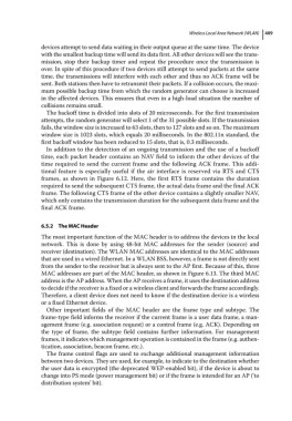
6.5.2 The MAC Header
The most important function of the MAC header is to address the devices in the local
network. This is done by using 48‐bit MAC addresses for the sender (source) and
receiver (destination). The WLAN MAC addresses are identical to the MAC addresses
that are used in a wired Ethernet. In a WLAN BSS, however, a frame is not directly sent
from the sender to the receiver but is always sent to the AP first. Because of this, three
MAC addresses are part of the MAC header, as shown in Figure 6.13. The third MAC
address is the AP address. When the AP receives a frame, it uses the destination address
to decide if the receiver is a fixed or a wireless client and forwards the frame accordingly.
Therefore, a client device does not need to know if the destination device is a wireless
or a fixed Ethernet device.
Other important fields of the MAC header are the frame type and subtype. The
frame‐type field informs the receiver if the current frame is a user data frame, a man-
agement frame (e.g. association request) or a control frame (e.g. ACK). Depending on
the type of frame, the subtype field contains further information. For management
frames, it indicates which management operation is contained in the frame (e.g. authen-
tication, association, beacon frame, etc.).
The frame control flags are used to exchange additional management information
between two devices. They are used, for example, to indicate to the destination whether
the user data is encrypted (the deprecated WEP‐enabled bit), if the device is about to
change into PS mode (power management bit) or if the frame is intended for an AP (‘to
distribution system’ bit).