
Page 43 - From GMS to LTE
P. 43
Global System for Mobile Communications (GSM) 29
0 1 2 3 4 5 6 7
t
Training Guard
Tail Data S S Data Tail
sequence time
t
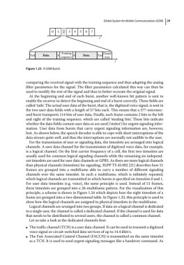
Figure 1.23 A GSM burst.
comparing the received signal with the training sequence and thus adapting the analog
filter parameters for the signal. The filter parameters calculated this way can then be
used to modify the rest of the signal and thus to better recreate the original signal.
At the beginning and end of each burst, another well‐known bit pattern is sent to
enable the receiver to detect the beginning and end of a burst correctly. These fields are
called ‘tails’. The actual user data of the burst, that is, the digitized voice signal, is sent in
the two user data fields with a length of 57 bits each. This means that a 577‐microsec-
ond burst transports 114 bits of user data. Finally, each frame contains 2 bits to the left
and right of the training sequence, which are called ‘stealing bits’. These bits indicate
whether the data fields contain user data or are used (‘stolen’) for urgent signaling infor-
mation. User data from bursts that carry urgent signaling information are, however,
lost. As shown below, the speech decoder is able to cope with short interruptions of the
data stream quite well, and thus the interruptions are normally not audible to the user.
For the transmission of user or signaling data, the timeslots are arranged into logical
channels. A user data channel for the transmission of digitized voice data, for example,
is a logical channel. On the first carrier frequency of a cell, the first two timeslots are
usually used for common logical signaling channels while the remaining six independ-
ent timeslots are used for user data channels or GPRS. As there are more logical channels
than physical channels (timeslots) for signaling, 3GPP TS 45.002 [21] describes how 51
frames are grouped into a multiframe able to carry a number of different signaling
channels over the same timeslot. In such a multiframe, which is infinitely repeated,
which logical channels are transmitted in which bursts is specified on timeslots 0 and 1.
For user data timeslots (e.g. voice), the same principle is used. Instead of 51 frames,
these timeslots are grouped into a 26‐multiframe pattern. For the visualization of this
principle, a scheme is shown in Figure 1.24 which depicts how the eight timeslots of a
frame are grouped into a two‐dimensional table. In Figure 1.25, this principle is used to
show how the logical channels are assigned to physical timeslots in the multiframe.
Logical channels are arranged into two groups. If data on a logical channel is dedicated
to a single user, the channel is called a dedicated channel. If the channel is used for data
that needs to be distributed to several users, the channel is called a common channel.
Let us take a look at the dedicated channels first:
The traffic channel (TCH) is a user data channel. It can be used to transmit a digitized
●
voice signal or circuit‐switched data services of up to 14.4 kbit/s.
The Fast Associated Control Channel (FACCH) is transmitted on the same timeslot
●
as a TCH. It is used to send urgent signaling messages like a handover command. As