
Page 474 - From GMS to LTE
P. 474
460 From GSM to LTE-Advanced Pro and 5G
ISO Application
7 RFCOMM / SDP
6 L2CAP
5 Host controller interface
4 Link manager
3 Link controller
2 Baseband (ACL, SCO or eSCO Link)
1 Radio layer
Figure 7.4 The Bluetooth protocol stack.
7.4.1 The Baseband Layer
The properties of the physical layer, that is, the radio transmission layer, have already
been described. On the basis of the physical layer, the baseband layer performs the typi-
cal duties of a layer 2 protocol, such as the framing of data packets. For the data transfer,
three different packet types have been defined in the baseband layer.
For packet data transmission, Bluetooth uses Asynchronous Connectionless (ACL)
packets. As shown in Figure 7.5, an ACL packet consists of a 68‐ to 72‐bit access code,
an 18‐bit header and a payload (user data) field of variable size between 0 and 2744 bits.
Before the 18 header bits are transmitted, they are coded into 54 bits by a Forward
Error Correction (1/3 FEC) algorithm. This ensures that transmission errors can be
corrected in most cases. Depending on the size of the payload field, an ACL packet
requires one, three or five slots of 625 microseconds.
The access code at the beginning of the packet is used primarily for the identification
of the piconet to which the current packet belongs. Thus, the access code is derived
from the device address of the piconet master. The actual header of an ACL packet
consists of a number of bits for the following purposes. The first three bits of the header
are the logical transfer address (LT_ADDR) of the slave, which the master assigns dur-
ing connection establishment. As three bits are used, up to seven slaves can be addressed.
After the LT_ADDR, the 4‐bit packet‐type field indicates the structure of the remain-
ing part of the packet. Table 7.2 shows the different ACL packet types. Apart from the
number of slots used for a packet, another difference is the use of FEC for the payload.
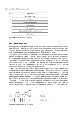
SEQN
LT_ADDR ARQN
Access Packet flow
code type HEC Payload
68–72 3 4 11 1 8 0–2744 Bits
Figure 7.5 Composition of an ACL packet.