
Page 43 - 3DA Mag N° February2018 -EN+
P. 43
The students thus developed the whole Engine likely under different loading conditions. Centrifugal
Monitoring System (EMS): from the design of the forces are also important on a model of this size and
traces for the Printed Circuit Boards (PCBs) to the failure scenarios are also modelled to assess if an
software and user interface. The EMS consists of: impact would be contained.
• 2 mbed micro-controllers “Our team is working to develop more advanced
models that are able to simulate the complex behaviour 3D Adept Mag
• Wireless (RF) transceivers of additively-manufactured parts”, said the students.
• 3 PCBs on the engine
• 2 IR temperature sensors
• 4 differential pressure sensors
• 2 LED rotational speed sensors
• 1 vibration sensor
• 1 airspeed sensor
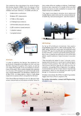
3D Printing
As far as 3D printing is concerned, they used a
DreamMaker OverLord Pro, often at full capacity. PLA,
ABS, nylon, PETG and more were the materials used
for tests. FFF was the only 3D printing technology used
for the X-Plorer 1 and throughout the testing phase,
they tried to optimise the process for the printer and
plastic used to achieve a major increase in success
rates.
Analysis
“The shorted print lasted for just 7 minutes, proto-
In order to optimize the design, the students first typing both brackets for securing the temperature
performed computational analysis to find out how sensors in their position. The main part of the PCU
the flow changes throughout the engine, as well as casing took 58 hours and 30 minutes non-stop to
the impact that specific forces and loading conditions complete, consuming 105m of filament in the making.
have on the parts. When several designs are available Loose tolerances can be a major issue in engineering
for one part, CFD analyses are performed with tools assemblies, which is why testing and altering the
that include Solidworks Flow Simulation, ANSYS Fluent design for the process is essential.”
& Star CCM+ on single stators, rotors or multi-stage Already a step ahead, the X-Plorer 2 will bring a better,
segments to assess which one performs the best.
bigger and more efficient engine to life.
FEA (Finite Element Analysis) were to discover high For further information, contact JetX Engineering,
stress concentrations and assess whether failure is
info@jet-x.org
Magazine / February 2018 43