
Page 16 - PBL71 OI/AXM630-EN AZTEC 600 SS (WIRO)
P. 16
Aztec 600 ISE ammonia and fluoride
Single-stream ion-selective analyzers
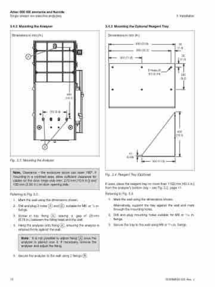
3.4.2 Mounting the Analyzer
Dimensions in mm (in.)
3 Installation
12
OI/AXM630–EN Rev. J
150 (5.9)
Fig. 3.3 Mounting the Analyzer
Note. Clearance – the enclosure doors can open 180°. If mounting in a confined area, allow sufficient clearance for cables on the door hinge side (min. 270 mm [10.6 in.]) and 100 mm (3.93 in.) on door opening side.
Referring to Fig. 3.3:
1. Mark the wall using the dimensions shown.
2. Drill and plug 3 holes A and B, suitable for M6 or 1/4 in. fixings.
3. Screw in top fixing A, leaving a gap of 20mm (0.78 in.) between the fixing head and the wall.
4. Hang the analyzer onto fixing A, ensuring the analyzer is retained firmly against the wall.
Note. It is not possible to adjust fixing A once the analyzer is placed over it. If necessary, remove the analyzer and adjust the fixing.
5. Secure the analyzer to the wall using 2 fixings B.
300 (11.8)
460 (18.1)
3.4.3 Mounting the Optional Reagent Tray
Dimensions in mm (in.)
300 (11.8)
10 (0.39)
Fig. 3.4 Reagent Tray (Optional)
600 (23.6) 565 (22.2)
35 (1.4)
35 (1.4)
235 (9.2)
6 Holes Ø 8.5 (0.34)
If used, place the reagent tray no more than 1100 mm (43.3 in.) from the analyzer’s bottom tray – see Fig. 3.2, page 11.
Referring to Fig. 3.4:
1.
2. 3.
Mark the wall using the dimensions shown.
Alternatively, support the tray against the wall and mark through the mounting holes.
Drill and plug mounting holes suitable for M8 or 5/16 in. fixings.
Secure the tray to the wall using M8 or 5/16 in. fixings.
400 (15.7)
