
Page 85 - PBL71 OI/AXM630-EN AZTEC 600 SS (WIRO)
P. 85
Aztec 600 ISE ammonia and fluoride
Single-stream ion-selective analyzers Appendix C – Principle of Operation – Ammonia Analyzers
Appendix C – Principle of Operation – Ammonia Analyzers
Solenoid valve and manifold assemblies
Standard solution (low)
Standard solution (high)
Sample from side sample pot
Reagent pump
Reagent
Ammonia flowcell
assembly (red) Waste
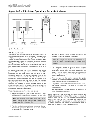
Fig. C.1 Flow Schematic
C.1 General Operation
The analyzer uses an ammonia probe. The probe contains a glass pH electrode (whose pH-sensitive glass membrane forms a slightly convex tip) and a robust, long-life reference electrode. The two electrodes are combined into a single assembly and are connected as a pH measuring pair through an internal reservoir of filling solution. The filling solution is 0.1 M ammonium chloride saturated with silver chloride and is separated from the sample by a gas-permeable hydrophobic membrane fitted to the tip of the probe.
As sample flows past the probe membrane, the partial pressures of the ammonia gas in the sample on one side of the membrane and the filling solution on the other equalize, transferring gas across the membrane. At equal pressure, the concentration of ammonia in the thin film of filling solution between the probe membrane and the pH-sensitive glass electrode membrane equals that in the sample. The resultant change in the pH value of the thin film is measured by the pH electrode pair, creating an output potential related to the ammonia concentration in the sample. Like most ion-selective electrodes, the ammonia probe produces an output that is logarithmic in respect to concentration.
The analyzer's sequence of operation is as follows:
1. Sample is supplied to a side sample pot constant head unit by a sample pump. Excess sample overflows to drain.
2. From the constant head unit, the sample is drawn through the normally open ports of solenoid valves SV1 and SV2 by one channel of a peristaltic pump.
3. Reagent is drawn through another channel of the peristaltic pump and mixed with the sample.
4. The conditioned sample is pumped into a flowcell containing the ammonia probe. The probe is enclosed in a heated block housing a heat-exchanger, ensuring that the body of the probe remains at a constant temperature and also at a temperature in agreement with that of the sample and standard solutions.
5. When exposed to the reacted sample, the probe produces an electrical potential that changes in proportion to the changes in activity of the measured ion.
6. The probe is connected to the electronics section where, after digital conversion, the signal is processed by microprocessor.
7. After measurement, the sample flows to waste via a contaminated drain connection.
During calibration, Low and High standard solutions are introduced sequentially in place of the sample by means of solenoid valves SV1 and SV2. The resultant millivolt Low and millivolt High readings from the probe are stored as the calibrated readings. The analyzer can be configured to perform automatic calibrations from every 6 hours to once per week. A calibration can also be initiated manually if required.
OI/AXM630–EN Rev. J
81
Note. The sample and reagent tube diameters are sized to obtain the correct ratio of sample and reagent.
Note. The constant head unit is fitted with a float switch that signals an 'Out-of-sample' condition by triggering an 'Out-of-Sample' alarm.
Conditioned sample
