
Page 167 - PBL614 IM/SM500F-EN SM500F ( WIRO)
P. 167
SM500F
Field mountable paperless recorder Appendix E – Math Equations
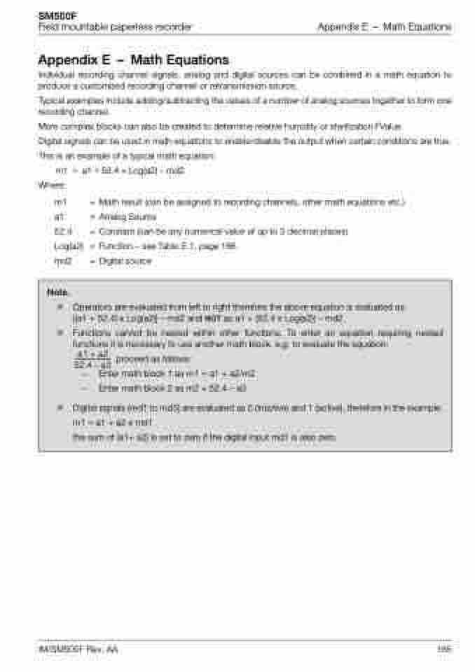
Appendix E – Math Equations
Individual recording channel signals, analog and digital sources can be combined in a math equation to produce a customized recording channel or retransmission source.
Typical examples include adding/subtracting the values of a number of analog sources together to form one recording channel.
More complex blocks can also be created to determine relative humidity or sterilization FValue.
Digital signals can be used in math equations to enable/disable the output when certain conditions are true. This is an example of a typical math equation:
m1 = a1+52.4Log(a2)–md2 Where:
m1 = Math result (can be assigned to recording channels, other math equations etc.) a1 = Analog Source
52.4 = Constant (can be any numerical value of up to 3 decimal places)
Log(a2) = Function – see Table E.1. page 166
md2 = Digital source
Note.
Operators are evaluated from left to right therefore the above equation is evaluated as: [(a1 + 52.4) x Log(a2)] – md2 and NOT as a1 + (52.4 x Log(a2)) – md2.
Functions cannot be nested within other functions. To enter an equation requiring nested functions it is necessary to use another math block, e.g. to evaluate the equation:
a1 + a2
-------------- proceed as follows: 52.4 – a3
– Entermathblock1asm1=a1+a2/m2 – Entermathblock2asm2=52.4–a3
Digital signals (md1 to md3) are evaluated as 0 (inactive) and 1 (active), therefore in the example: m1 = a1 + a2 x md1
the sum of (a1+ a2) is set to zero if the digital input md1 is also zero.
IM/SM500F Rev. AA 165
