
Page 25 - PBL614 IM/SM500F-EN SM500F ( WIRO)
P. 25
SM500F
Field mountable paperless recorder 2 Installation
2.9.3 Pull-up and Pull-down Resistors
To prevent false triggering of slaves when the master (host computer) is inactive, pull-up and pull-down resistors are fitted to the SM500F's Modbus/digital input module.
2.9.4 Termination Resistor
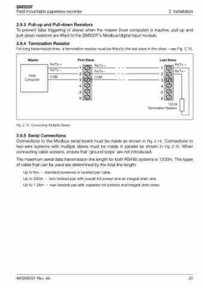
For long transmission lines, a termination resistor must be fitted to the last slave in the chain – see Fig. 2.15.
Host Computer
Rx/Tx –
Master
First Slave Last Slave
Rx/Tx +
Rx/Tx + Rx/Tx –
COM
Rx/Tx +
11
Rx/Tx –
22
COM
33 44 55 66
120 Termination Resistor
Fig. 2.15 Connecting Multiple Slaves
2.9.5 Serial Connections
Connections to the Modbus serial board must be made as shown in Fig. 2.14. Connections to two-wire systems with multiple slaves must be made in parallel as shown in Fig. 2.15. When connecting cable screens, ensure that 'ground loops' are not introduced.
The maximum serial data transmission line length for both RS485 systems is 1200m. The types of cable that can be used are determined by the total line length:
Up to 6m – standard screened or twisted pair cable.
Up to 300m – twin twisted pair with overall foil screen and an integral drain wire. Up to 1.2km – twin twisted pair with separate foil screens and integral drain wires.
IM/SM500F Rev. AA 23
