
Page 343 - statbility for masters and mates
P. 343
Shear Force and Bending Moment Diagrams
The shear forces and bending moments created in a beam which is supported and loaded in a particular way can be illustrated graphically.
Consider ®rst the case of cantilevers which are supported at one end only.
Case I
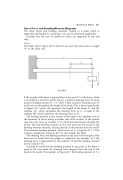
The beam AB in Figure 40.6 is ®xed at one end only and carries a weight `W' at the other end.
Bending of beams 331
Fig. 40.6
If the weight of the beam is ignored then at any point Y in the beam, which is at distance X from the end B, there is a positive shearing force W and a positive bending moment W X. There is thus a positive shearing force W at all sections throughout the length of the beam. This is shown graphically in Figure 40.7 where AB represents the length of the beam (l), and the ordinate AC, which represents the shearing force at A, is equal to the ordinate BD which represents the shearing force at B.
The bending moment at any section of the beam is the algebraic sum of the moments of forces acting on either side of the section. In the present case, the only force to consider is W which acts downwards through the end B. Thus the bending moment at B is zero and from B towards A the bending moment increases, varying directly as the distance from the end B. The maximum bending moment, which occurs at A, is equal to W l. This is shown graphically in Figure 40.7 by the straight line BGE.
The shearing force and bending moment at any point in the length of the beam can be found from the graph by inspection. For example, at Y the shearing force is represented by the ordinate YF and the bending moment by the ordinate YG.
It should be noted that the bending moment at any point in the beam is equal to the area under the shearing force diagram from the end of the beam to that point. For example, in Figure 40.7, the bending moment at Y is
