
Page 1247 - 2006 HARLEY FLSTCI SERVICE MANUAL
P. 1247
6.2
5 4 3
5 2
bled again and plate movement checked again.
1
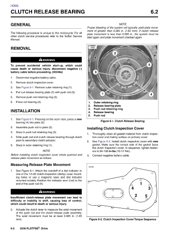
NOTE Proper bleeding of the system will typically yield plate move- ment of greater than 0.065 in. (1.65 mm). If clutch release plate movement is less than 0.065 in., the system must be Figure 6-1. Clutch Release Bearing Thoroughly clean all gasket material from clutch inspec- tion cover and mating surface on primary cover. See Figure 6-2. Install clutch inspection cover with new gasket. Make sure the correct side of the gasket faces the clutch inspection cover. In sequence, tighten fasten- 4 Figure 6-2. Clutch Inspection Cover Torque Sequence
Outer retaining ring Release bearing plate Push rod retaining ring
2 Installing Clutch Inspection Cover ers to 84-108 in-lbs (10-12 Nm). Connect negative battery cable.
1 Release bearing Push rod
3
10950 o9199
1. 2. 3. 4. 5.
1. 2. 3.
CLUTCH RELEASE BEARING
other clutch service procedures refer to the Softail Service
The following procedure is unique to this motorcycle. For all
1WARNING 1WARNING prevent accidental vehicle start-up, which could cause death or serious injury, disconnect negative (-) battery cable before proceeding. (00048a) Disconnect negative battery cable. Remove clutch inspection cover. See Figure 6-1. Remove outer retaining ring (1). Pull out release bearing plate (2) with push rod (5). Remove push rod retaining ring (3). See Figure 6-1. Pressing on the outer race, press a new Assemble push rod to plate (2). Snap in push rod retaining ring (3). Slide push rod and clutch release bearing through clutch pack to secondary clutch actuator. Snap in outer retaining ring (1). NO
GENERAL REMOVAL Press out bearing (4). INSTALLATION bearing (4) into plate (2). release plate movement as follows. end of the push rod (5). mm). 2006 FLSTFSE 2 : Drive
HOME Manual. To 1. 2. 3. 4. 5. 6. 1. 2. 3. 4. 5. 1. 2. 6-2