
Page 793 - 2006 HARLEY FLSTCI SERVICE MANUAL
P. 793
3.4 8
9
5
4
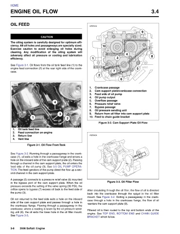
6 Cam support plate/crankcase connection Return from oil filter into cam support plate Figure 3-2. Cam Support Plate Oil Flow Figure 3-3. Oil Filter Flow After circulating through the oil filter, the flow of oil is directed back into the crankcase through the spigot in the oil filter mount. See Figure 3-2. Exiting a passageway in the crank- case through a hole in the crankcase flange, the flow of oil Filtered oil is then routed to the top and bottom ends of the engine. See TOP END, BOTTOM END and CHAIN GUIDE
Crankcase passage Feed side of oil pump Overflow passage Pressure relief valve reenters the cam support plate (9).
3
7 Oil pressure sending unit Feed to chain guide bracket
10 Oil pump output Bypass passage
2 BRACKET which follow.
s0264x3x 1 1. 2. 3. 4. 5. 6. 7. 8. 9. 10. s0263x3x
2
3
ENGINE OIL FLOW CAUTION The oiling system is carefully designed for optimum effi- ciency. All oil holes and passageways are specially sized. Exercise caution to avoid enlarging oil holes during cleaning. Any modification of the oiling system will adversely affect oil pressure or cooling and lubrication See Figure 3-1. Oil flows from the oil tank feed line (1) to the engine feed connection (2) at the rear right side of the crank- 1 Oil tank feed line Feed connection on engine Return line Figure 3-1. Oil Flow From Tank See Figure 3-2. Running through a passageway in the crank- case (1), oil exits a hole in the crankcase flange and enters a hole on th
4
HOME OIL FEED efficiency. case. 7510 1. 2. 3. Vent line 4. the pump (3). See Figure 3-3. 3-6