
Page 116 - ro membanes
P. 116
5.2 BAR, BAND, AND DRUM SCREENS 99
of polyamide, polyester, or super duplex stainless steel for seawater applications and duplex stainless steel for brackish water intakes. The debris accumulation causes gradual increase in screen headlosses. Once the headlosses reach a certain preset level (or based on a preset time), the screening panels are rotated upwards the debris collected on the panels are moved to the deck level where they are removed from the panels into collection troughs by low-pressure water sprays. The debris is either conveyed to collection bins and disposed as solid waste or is recycled back to the source water body.
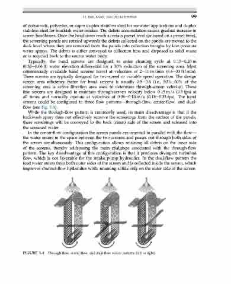
Typically, the band screens are designed to enter cleaning cycle at 0.10e0.20m (0.33e0.66 ft) water elevation differential for a 30% reduction of the screening area. Most commercially available band screens travel at velocities of 2e10 m/min (6.6e33 ft/min). These screens are typically designed for two-speed or variable speed operation. The design screen area efficiency factor for band screens is usually 0.5e0.6 (i.e., 50%e60% of the screening area is active filtration area used to determine through-screen velocity). These fine screens are designed to maintain through-screen velocity below 0.15 m/s (0.5 fps) at all times and normally operate at velocities of 0.06e0.10 m/s (0.18e0.33 fps). The band screens could be configured in three flow patternsdthrough-flow, center-flow, and dual- flow (see Fig. 5.4).
While the through-flow pattern is commonly used, its main disadvantage is that if the backwash spray does not effectively remove the screenings from the surface of the panels, these screenings will be conveyed to the back (clean) side of the screen and released into the screened water.
In the center-flow configuration the screen panels are oriented in parallel with the flowd the water enters in the space between the two screens and passes out through both sides of the screen simultaneously. This configuration allows retaining all debris on the inner side of the screens, thereby addressing the main challenge associated with the through-flow pattern. The key disadvantage of this configuration is that it produces divergent turbulent flow, which is not favorable for the intake pump hydraulics. In the dual-flow pattern the feed water enters from both outer sides of the screen and is collected inside the screen, which improves channel-flow hydraulics while retaining solids only on the outer side of the screen.
FIGURE 5.4 Through-flow, center-flow, and dual-flow screen patterns (left to right).
