
Page 159 - ro membanes
P. 159
142 7. SAND REMOVAL, SEDIMENTATION, AND DISSOLVED AIR FLOTATION
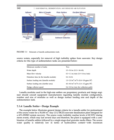
FIGURE 7.3 Schematic of lamella sedimentation tank.
source waters, especially for removal of high turbidity spikes from seawater. Key design criteria for this type of sedimentation tanks are presented below:
Minimum number of tanks
Water depth
Mean flow velocity
Detention time (in the lamella module) Surface loading rate (lamella module) Surface loading rate (clarifier area) Sludge collector speed
Two
3.5e5.0 m (11.5e16.4 ft)
0.3e1.1 m/min (1.0e3.6 m/min) 0.2e0.4 h
1.0e2.0 m3/m2 h (0.4e0.8 gpm/ft2) 4.0e8.0 m3/m2 h (1.6e3.2 gpm/ft2) 0.4e0.8 m/min (for collection path)
Lamella modules used in the high-rate settlers are proprietary products and design engi- neer should consult equipment manufacturers regarding lamella module configuration, number and size of modules as well as design surface loading rate and depth of the sedimentation tank.
7.3.4 Lamella SettlerdDesign Example
The example below illustrates general design criteria for a lamella settler for pretreatment of the source water for a 50,000 m3/day (13.2 MGD) seawater desalination plant designed for a 43%-SWRO system recovery. The source water turbidity reaches levels of 80 NTU during storm events, which may last several days and therefore, the plant is equipped with a com- bination of lamella settlers followed by a single-stage-dual granular media filters. The source water quality is relatively low in terms of hydrocarbon contentdwith maximum
