
Page 160 - ro membanes
P. 160
Component/Parameter
FEED WATER
• Design flow rate, m3/day (MGD) • Turbidity, NTU
• SDI2.5
• Algal content, cells/L
DESIGN CHEMICAL DOSAGES
• Ferric chloride, mg/L
• Cationic polymer, mg/L
• Sulfuric acid, mg/Ldtarget pHd6.7
• Number of settler tanks
• Number of lamella modules per tank • Width of lamella modules, m (ft)
• Length of lamella modules, m (ft)
• Depth of lamella modules, m (ft)
• Net surface area per lamella module • Surface loading rate/module area
• Setter tank surface area
• Settler tank surface loading rate
• Water depth
Specifications/Design Criteria
127,910 (33.8 MGD) 0.5e80
6e16
<20,000
15 (0.5e50 mg/L) 0.5 (0.0e1.0 mg/L) 8 (0e30 mg/L)
4
4
1.24(4.1 ft)
8.67 (28.4 ft)
2.588 (9.8 ft)
235 m2 (2528 ft2)
1.42 m3/m2 h/(0.6 gpm/ft2) 43 m2 (463 ft2)
7.7 m3/m2 h (3.1 gpm/ft2) 5.5 m (20.8 ft)
7.3 SEDIMENTATION TANKS 143
concentration of 0.04 mg/L or less. The source water is not frequently exposed to algal blooms, and when such events occur periodically they are of low intensitydwith algal con- tent of the source water of 20,000 cells/L, or less.
The plant filter backwash flow is 8.5% of the intake flow and lamella clarifier waste stream (sludge) flow is 0.6% of the intake plant flow. The pretreatment system is designed to operate with addition of coagulant, flocculant, and pH adjustment of the source water flow.
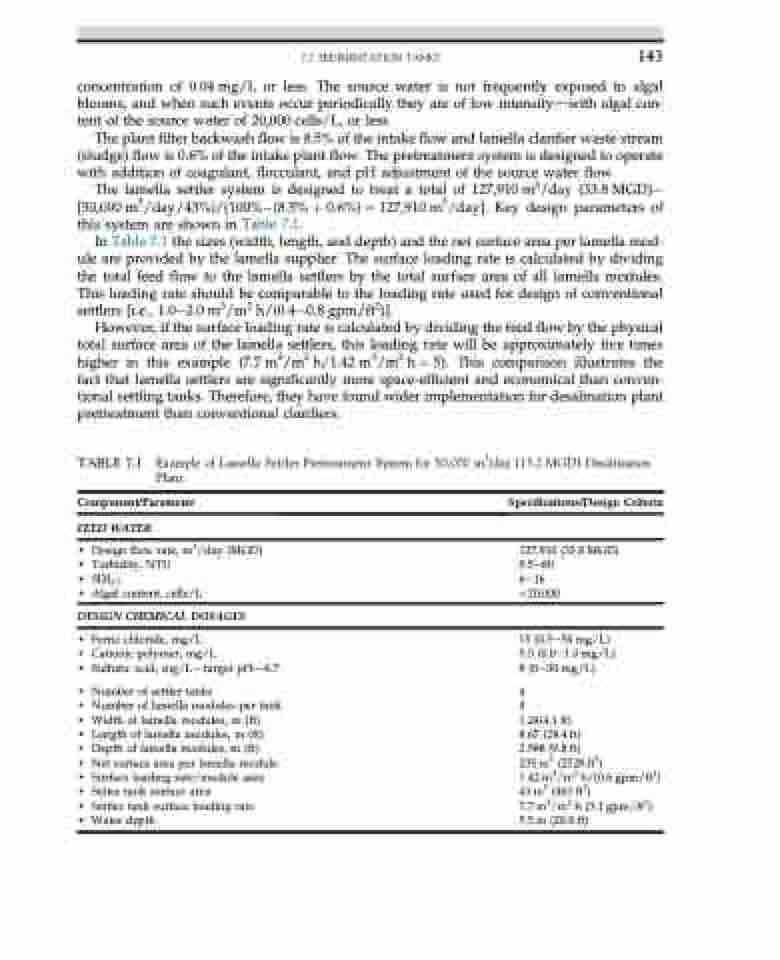
The lamella settler system is designed to treat a total of 127,910 m3/day (33.8 MGD) [50,000 m3/day/43%)/(100%(8.5% þ 0.6%) 1⁄4 127,910 m3/day]. Key design parameters of this system are shown in Table 7.1.
In Table 7.1 the sizes (width, length, and depth) and the net surface area per lamella mod- ule are provided by the lamella supplier. The surface loading rate is calculated by dividing the total feed flow to the lamella settlers by the total surface area of all lamella modules. This loading rate should be comparable to the loading rate used for design of conventional settlers [i.e., 1.0e2.0 m3/m2 h/(0.4e0.8 gpm/ft2)].
However, if the surface loading rate is calculated by dividing the feed flow by the physical total surface area of the lamella settlers, this loading rate will be approximately five times higher in this example (7.7 m3/m2 h/1.42 m3/m2 h 1⁄4 5). This comparison illustrates the fact that lamella settlers are significantly more space-efficient and economical than conven- tional settling tanks. Therefore, they have found wider implementation for desalination plant pretreatment than conventional clarifiers.
TABLE 7.1 Example of Lamella Settler Pretreatment System for 50,000 m3/day (13.2 MGD) Desalination Plant
