
Page 215 - ro membanes
P. 215
198
9. MEMBRANE FILTRATION
FIGURE 9.3
Pressurized membrane filtration system with vertical membrane elements.
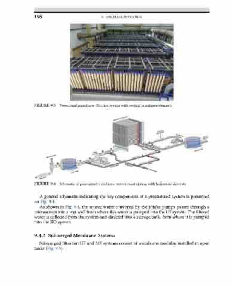
FIGURE 9.4
Schematic of pressurized membrane pretreatment system with horizontal elements.
A general schematic indicating the key components of a pressurized system is presented on Fig. 9.4.
As shown in Fig. 9.4, the source water conveyed by the intake pumps passes through a microscreen into a wet well from where this water is pumped into the UF system. The filtered water is collected from the system and directed into a storage tank, from where it is pumped into the RO system.
9.4.2 Submerged Membrane Systems
Submerged filtration UF and MF systems consist of membrane modules installed in open tanks (Fig. 9.5).
