
Page 216 - ro membanes
P. 216
9.4 FILTER TYPES AND CONFIGURATIONS 199
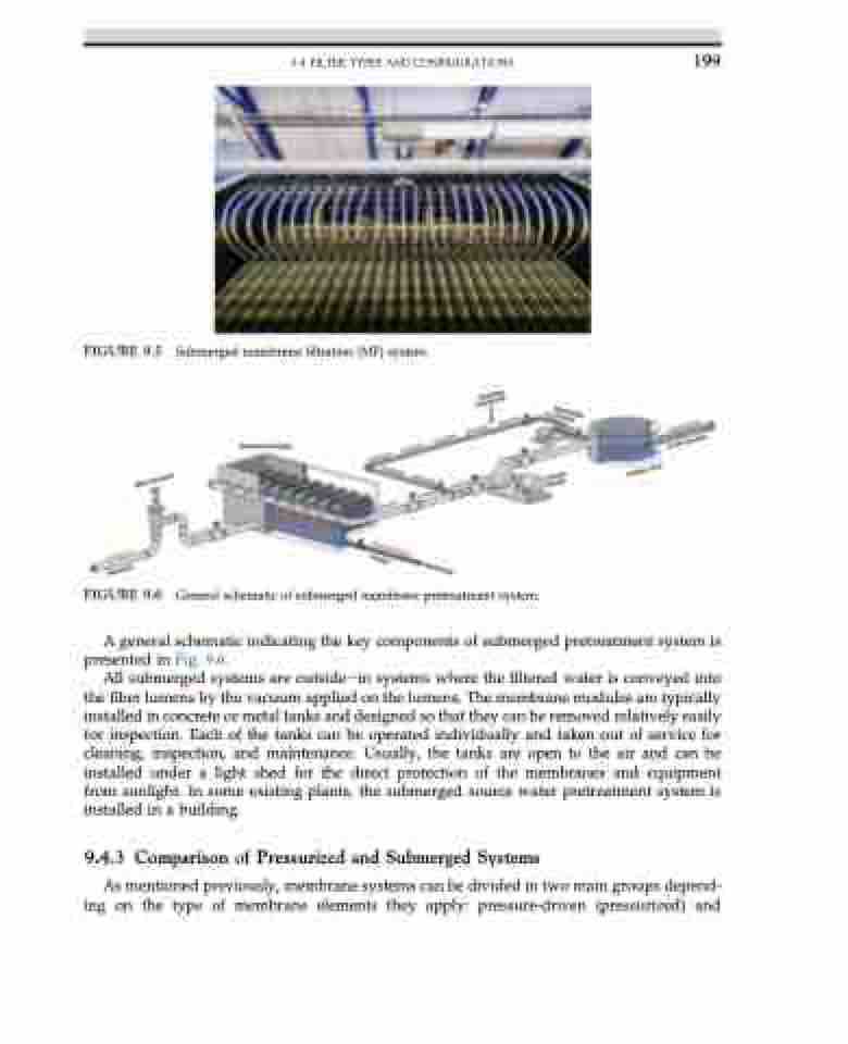
FIGURE 9.5 Submerged membrane filtration (MF) system.
FIGURE 9.6 General schematic of submerged membrane pretreatment system.
A general schematic indicating the key components of submerged pretreatment system is presented in Fig. 9.6.
All submerged systems are outsideein systems where the filtered water is conveyed into the fiber lumens by the vacuum applied on the lumens. The membrane modules are typically installed in concrete or metal tanks and designed so that they can be removed relatively easily for inspection. Each of the tanks can be operated individually and taken out of service for cleaning, inspection, and maintenance. Usually, the tanks are open to the air and can be installed under a light shed for the direct protection of the membranes and equipment from sunlight. In some existing plants, the submerged source water pretreatment system is installed in a building.
9.4.3 Comparison of Pressurized and Submerged Systems
As mentioned previously, membrane systems can be divided in two main groups depend- ing on the type of membrane elements they apply: pressure-driven (pressurized) and
