
Page 262 - L-com products 2018 e-magazine catalog
P. 262
260
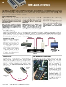
Test Equipment Tutorial
Cable and Network Test Equipment is vital to the uptime of any datacom system. Reports have shown that up to 70% of network downtime can be traced
to the physical layer or a cable. By implementing basic go-no-go cable testers as well as more advanced network test and troubleshooting tools, network
downtime can be greatly reduced. L-com offers testers for coax, Cat5e (or better), fiber optic, and RJ11/12 cabling and power. Additionally we offer
environmental testers to measure light, sound and temperature.
Network Cable Testing Terms
NEXT: Near End Cross Talk. A signal that crosses Propagation Delay Skew: Used to define the conductors. Return loss failures are often caused by
between twisted pairs or between conductors. NEXT is difference in signal speed between the fastest and cable impedance problems.
measured at the transmission end (near end). Measured slowest pair within a cable. It can also define the delay
in dB, failures for this measurement are often caused within an individual pair. Must be <45ns for a 4-pair Return Loss: The ratio of reflected power to inserted
by termination problems. horizontal cable. power. It is the measure of the signal reflections
occurring along a network cable system. It is often
FEXT: Far End Cross Talk. Crosstalk that is measured on Impedance: Measure of the total opposition a circuit caused by imperfections in the cable conductors,
the conductors that are not being used for transmission offers to the flow of alternating current. Target impedance mismatches or bad contacts in a plug
at the receiver or far end of the transmission. Measured impedance for UTP and STP cable is 100 Ohms. This or jack.
in dB, failures for this measurement are often caused can be affected by the twist of the conductors along
by termination problems. with the thickness of the insulation around the
Network Channel Testing
Network Channel Testing is a method used to verify performance from the workstation to the hub/switch including patch cords. Channel Testing is not
accurate for individual patch cords. Both installers and IT professionals conduct this type of testing to insure that the entire cable system is capable of
handling network traffic. Channel Testing differs from Permanent Link Testing in that it includes the patch cords on both ends of the installation.
Often, patch cords are overlooked as the cause of network failures.
Permanent Link Testing Patch Cable Patch Cable Patch Cable
Permanent Link Testing is the preferred
method used by installers to certify a
cable installation at a customer site. This
type of testing verifies the installation by
measuring many factors such as cable
lengths, NEXT, FEXT and Return Loss.
Several certification testers exist on the
market including Fluke Networks Hub/Switch Wall Plate
DTX-1800 series products. This type of
tester features a Permanent Link adapter
that connects from a workstation outlet Workstation
to the telecom closet outlet. Patch Panel
Continuity Testing Wire Mapping/LAN and Cable Testing
Continuity Testing is the most basic form of testing conducted on If you require more than just a standard continuity test you might
cables. These types of testers look for opens, shorts or crossed consider a Wire Mapping tester like the AEMC-CA7028. With a tester
connections. For Ethernet, this type of testing does not confirm network like this you would get a more
transmission capability. The most common mistake in cable pin-out is detailed report of how your
an EIA568 A to B cross. A simple continuity tester such as the cable is wired/paired. All
TL-N044-000-R, can easily find this error without the expense of a faults and setting info is
certification tester. displayed textually as well
as graphically. But beyond
TL-N044-000-R that with TDR technology it
Remote
can determine if the fault lies
at the near end or remote end
of the cable or if it is
somewhere in between. It can
even indicate the distance to
TL-N044-000-R
Master the fault as well as determine
the length of the cable or
Patch Cable cable run being tested.
L-com.com | 800-343-1455 | sales@L-com.com