
Page 34 - Pocket Guides
P. 34
POCKET GUIDE 19
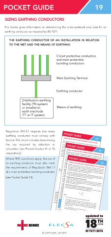
SIZING EARTHING CONDUCTORS
This Guide gives information on determining the cross-sectional area (csa) for an
earthing conductor as required by BS 7671.
THE EARTHING CONDUCTOR OF AN INSTALLATION IN RELATION
TO THE MET AND THE MEANS OF EARTHING
Circuit protective conductors
and main protective
bonding conductors
Main Earthing Terminal
Earthing conductor
Distributor’s earthing
facility (TN system)
or installation Means of earthing
earth electrode
(TT or IT system)
Regulation 542.3.1 requires that every
earthing conductor must comply with POCKET GUIDE
13
Section 543, which includes determining SIZING MAIN PROTECTIVE BONDING CONDUCTORS
the csa required by selection or This Guide gives information on the sizing of main protective bonding conductors,
based on the requirements given in Regulation Group 544.1 of BS 7671.
calculation (see Pocket Guides 14 or 15, protection for protection against electric shock where the protective measure is 14
POCKET GUIDE
Protective equipotential bonding is a provision under the requirements for fault
Automatic Disconnection of Supply (ADS).
respectively). Where the protective measure is ADS, in each installation main protective bonding
ARRANGEMENT OF PROTECTIVE EQUIPOTENTIAL BONDING
SIZING OF PROTECTIVE CONDUCTORS BY SELECTION
Regulation Group 543.1 of BS 7671 requires that a protective conductor other than
Where PME conditions apply, the csa of the main earthing terminal the extraneous-conductive-parts of that installation
conductors complying with Chapter 54 of BS7671 are required to connect to
protective bonding conductor is sized either by calculation or selection.This guide
covers the sizing of protective conductors by selection, using Table 54.7.
• water installation pipes
POCKET GUIDE
an earthing conductor must also meet • other installation pipework and ducting
including: It should be noted that where the choice of the cross-sectional-area (csa) of the line
• gas installation pipes
conductors has been determined by considerations of short-circuit current, and if 15
of the protective conductor must be calculated (543.1.1).
the earth fault current is expected to be less than the short-circuit current, the csa
MINIMUM PROTECTIVE CONDUCTOR SIZES
the requirements of Regulation 544.1.1 • exposed metallic structural parts of the building.
SIZING OF PROTECTIVE CONDUCTORS BY CALCULATION
• central heating and air conditioning systems
Regulation Group 543.1 of BS 7671 requires that a protective conductor other
than an protective bonding conductor is sized either by calculation or
of a main protective bonding conductor with BS EN 62305 (411.3.1.2).
Certain lower limits apply to the csa of a protective conductor. The size of the selection.
protective conductor used must be not less than the appropriate limiting value (see
below) and not less than that determined by selection (see later).
This Guide covers the sizing of protective conductors by calculation, which uses
conductors by selection is given in Pocket Guide 14.
the adiabatic equation, as explained later. Information on sizing of protective
Any bonding to a lightning protection system must be carried out in accordance
Where a protective conductor is not an integral part of a cable (such as a ‘twin & earth’
(see Pocket Guide 13). Pocket Guide 13).
cable or an armoured cable); or formed by conduit, ducting or trunking; or contained
in an enclosure formed by a wiring system, the csa of the protective conductor must
Extraneous-conductive-part
A protective conductor must always be sized by calculation where the line conductor
other than pipework
has been sized by considerations of short-circuit current and if the earth fault current
is expected to be less than the short-circuit current (543.1.1).
not be less than 2.5 mm 2 copper equivalent if protection against mechanical damage
(eg exposed structural metalwork)
MINIMUM PROTECTIVE CONDUCTOR SIZES
protection against mechanical damage is not provided (543.1.1).
is provided (such as by a sheath), and not less than 4 mm 2 copper equivalent if
Where PME conditions apply, a protective conductor used as an earthing conductor
Certain lower limits apply to the cross-sectional-area (csa) of the protective
discussed in Pocket Guide 14.
Main protective
conductor. The size of the protective conductor used must not be less than the
must have a csa not less than that required by Regulation 544.1.1 (refer to NICEIC
bonding conductors
limiting values given in Regulations 543.1.1 and, where applicable, 544.1.1 as
required by Table 54.1 of BS 7671.
Water
Gas
meter
A protective conductor buried in the ground must have a csa not less than that
CALCULATING THE SIZE OF THE PROTECTIVE CONDUCTOR
meter
SELECTING THE SIZE OF THE PROTECTIVE CONDUCTOR
Main Earthing Terminal
The csa of the protective conductor, where calculated, is to be no less than the
value (S) determined using the adiabatic equation (543.1.3).
Metallic
pipework
S = I 2 t
The process of selection uses the csa (S) of the associated line conductor and
Where: k
Table 54.7 of BS 7671 (Data reproduced below in part). Where the protective
be used.
conductor is common to several circuits, its csa should be based on the csa of the
S
WHERE PROTECTIVE MULTIPLE EARTHING (PME) CONDITIONS DO NOT APPLY
largest line conductor of the circuits (543.1.2). Where selection produces a non-
I is the nominal csa of the protective conductor in mm 2 .
DATA FROM TABLE 54.7 OF BS 7671
Where PME conditions do not apply, Regulation 544.1.1 requires a main protective
standard size, a conductor having at least the nearest larger standard csa should
bonding conductor to have a cross-sectional area (csa) of not less than half the csa
required for the earthing conductor of the installation, and not less than 6 mm 2 .
conductor S (mm 2 )
S ≤ 16
affording equivalent conductance in other metals.
The csa need not exceed 25 mm 2 if the bonding conductor is of copper, or a csa
is the value in amperes (rms for AC) of the fault current for a fault
Minimum csa of the
16 < S ≤ 35
WHERE PME CONDITIONS APPLY
CSA of line of negligible impedance, which can flow through the associated
A S > 35
corresponding
protective device.
t S
protective device, due account being taken of the current limiting
protective conductor
(mm 2 ) 16 S
effect of the circuit impedances and the limiting capability (I 2 t) of that
B 2
S
k 1
k corresponding to the fault current (I) in amperes. k 1
X 16
k 2 updated to S
is the operating time of the disconnecting device in seconds
X 2
k 2
TH
Row B of the above table, as applicable.
BS 7671:2018 updated to
EDITION
The csa of the protective conductor must be not less than required by Row A or
© CERTSURE LLP 2019
is a factor taking account of the resistivity, temperature coefficient and
final temperatures of the conductors.
heat capacity of the conductor material, and the appropriate initial and
Row A should be used where the protective conductor
is of the same material as the associated line conductor.
nearest larger standard csa should be used.
Row B should be used where the protective conductor is
updated to TH
Where a non-standard size is calculated, a conductor having at least the
not of the same material as the associated line conductor.
TH updated to
EDITION
Where the protective conductor is common to several circuits, the calculation
circuits (543.1.2). EDITION
TH
process should be based on the most onerous values of fault current (I) and
BS 7671:2018
EDITION
operating time (t) (or energy let-through (I 2 t)) encountered in each of the
© CERTSURE LLP 2019
BS 7671:2018
BS 7671:2018
© CERTSURE LLP 2019
updated to
TH
updated to
EDITION
TH
BS 7671:2018
EDITION
© CERTSURE LLP 2019
updated to
BS 7671:2018
updated to
TH
TH
EDITION
EDITION
BS 7671:2018
BS 7671:2018