
Page 313 - Installation Training Binder FIT1-3
P. 313
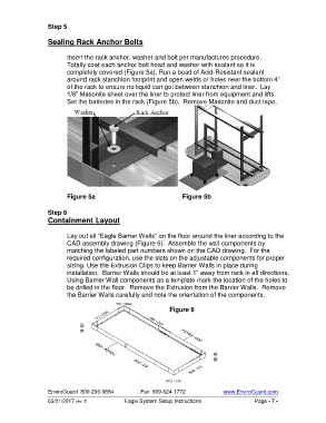
Step 5

                   Sealing Rack Anchor Bolts

                          Insert the rack anchor, washer and bolt per manufactures procedure.
                          Totally coat each anchor bolt head and washer with sealant so it is
                          completely covered (Figure 5a). Run a bead of Acid-Resistant sealant
                          around rack stanchion footprint and open welds or holes near the bottom 4”
                          of the rack to ensure no liquid can get between stanchion and liner.  Lay
                          1/8” Masonite sheet over the liner to protect liner from equipment and lifts.
                          Set the batteries in the rack (Figure 5b).  Remove Masonite and duct tape.


                          Figure 5a                                                 Figure 5b

                   Step 6
                   Containment Layout

                          Lay out all “Eagle Barrier Walls” on the floor around the liner according to the
                          CAD assembly drawing (Figure 6).  Assemble the wall components by
                          matching the labeled part numbers shown on the CAD drawing.  For the
                          required configuration, use the slots on the adjustable components for proper
                          sizing. Use the Extrusion Clips to keep Barrier Walls in place during
                          installation.  Barrier Walls should be at least 1” away from rack in all directions.
                          Using Barrier Wall components as a template mark the location of the holes to
                          be drilled in the floor.  Remove the Extrusion from the Barrier Walls.  Remove
                          the Barrier Walls carefully and note the orientation of the components.

                                                                 Figure 6


                   EnviroGuard  800-206-9884          Fax  909-624-1772              www.EnviroGuard.com
                   03/01/2017 rev. E            Eagle System Setup Instructions                  Page - 7 -