
Page 199 - icripe2020
P. 199
TinkerCAD is a free online service for creating of electronic circuits. This application includes basic circuits with LED
lights, buzzers, switches and even light sensors. This application also can include a microprocessor as part of the design.
Students can develop components in a flexible manner than can be quickly updated and modified to test a variety of options
when developing a circuit. Student will use this process to learn how to create basic electronic circuits. TinkerCAD integrates
with Microsoft, Google and also social media services like Facebook. Students can use their personal or institution email
account to log into Autodesk TinkerCAD.
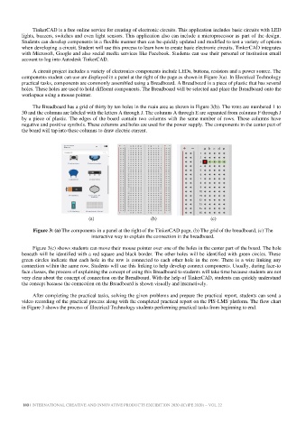
A circuit project includes a variety of electronics components include LEDs, buttons, resistors and a power source. The
components student can use are displayed in a panel at the right of the page as shown in Figure 3(a). In Electrical Technology
practical tasks, components are commonly assembled using a Breadboard. A Breadboard is a piece of plastic that has several
holes. These holes are used to hold different components. The Breadboard will be selected and place the Breadboard onto the
workspace using a mouse pointer.
The Breadboard has a grid of thirty by ten holes in the main area as shown in Figure 3(b). The rows are numbered 1 to
30 and the columns are labeled with the letters A through J. The columns A through E are separated from columns F through J
by a piece of plastic. The edges of the board contain two columns with the same number of rows. These columns have
negative and positive symbols. These columns and holes are used for the power supply. The components in the center part of
the board will tap into these columns to draw electric current.
(a) (b) (c)
Figure 3: (a) The components in a panel at the right of the TinkerCAD page, (b) The grid of the breadboard, (c) The
interactive way to explain the connection in the breadboard.
Figure 3(c) shows students can move their mouse pointer over one of the holes in the center part of the board. The hole
beneath will be identified with a red square and black border. The other holes will be identified with green circles. These
green circles indicate that each hole in the row is connected to each other hole in the row. There is a wire linking any
connection within the same row. Students will use this linking to help develop connect components. Usually, during face-to
face classes, the process of explaining the concept of using this Breadboard to students will take time because students are not
very clear about the concept of connection on the Breadboard. With the help of TinkerCAD, students can quickly understand
the concept because the connection on the Breadboard is shown visually and interactively.
After completing the practical tasks, solving the given problems and prepare the practical report, students can send a
video recording of the practical process along with the completed practical report on the PIS-LMS platform. The flow chart
in Figure 3 shows the process of Electrical Technology students performing practical tasks from beginning to end.
180 | INTERNATIONAL CREATIVE AND INNOVATIVE PRODUCTS EXHIBITION 2020 (ICrIPE 2020) – VOL 22