
Page 594 - SUBSEC October 2017_Neat
P. 594
PRACTICAL ACTIVITIES (cont’d)
THE GAIN OF AN INVERTING AMPLIFIER
Refer to Unit 2, Module 2, Specific Objective 4.11
Aim: To plot the transfer characteristic of an op. amp. connected as an inverting amplifier
and measure its gain.
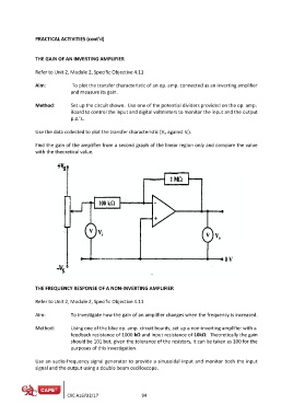
Method: Set up the circuit shown. Use one of the potential dividers provided on the op. amp.
Board to control the input and digital voltmeters to monitor the input and the output
p.d.’s.
Use the data collected to plot the transfer characteristic (Vo against Vi).
Find the gain of the amplifier from a second graph of the linear region only and compare the value
with the theoretical value.
THE FREQUENCY RESPONSE OF A NON-INVERTING AMPLIFIER
Refer to Unit 2, Module 2, Specific Objective 4.11
Aim: To investigate how the gain of an amplifier changes when the frequency is increased.
Method: Using one of the blue op. amp. circuit boards, set up a non-inverting amplifier with a
feedback resistance of 1000 kΩ and input resistance of 10kΩ. Theoretically the gain
should be 101 but, given the tolerance of the resistors, it can be taken as 100 for the
purposes of this investigation.
Use an audio-frequency signal generator to provide a sinusoidal input and monitor both the input
signal and the output using a double beam oscilloscope.
CXC A16/U2/17 94