
Page 102 - ARCHIDOCT 6-2
P. 102
102
ISSN 2309-0103 www.enhsa.net/archidoct Vol. 6 (2) / February 2019
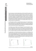
The point clouds were processed and separated for each lamella using the Volvox plugin for Grass- hopper.A Grasshopper script extracted the design features from the point clouds.A mesh is gen- erated from the point clouds, and the top and bottom edge of the lamellas were computed as curves, and represented in the digital model (Figure 6). The extracted curves served as input for the parametric design algorithm. Showing the advantage of digital computation, we implemented an interpolation strategy to create differentiated geometries based on the inputs.The extracted features were interpreted by the algorithm to construct a series of lamellas.The distance between the top edges and bottom edges of the input lamellas was measured and equally divided to draw the digital lamellas. Graph mappers integrated into the interpolation design tool allowed the user to control the positioning, orientation and rotation of the interpolated lamellas through a numerical differentiation based on visual input (Figure 7).
The lamellas follow the definition of ruled geometries. As such, they can be described through a series of straight lines, which are called generators (Figure 8) (Pottmann et al., 2007). Already, the physical input lamellas follow this logic through the placed rods. For the robotic construction, the rod positions, directions, and associated planes were extracted from the digital lamella model based on the surfaces generators (Figure 9).Those were simulated with the Grasshopper-Plugin Robots and then sent to the robot for precise arrangement (Figure 10).
The assembly process was divided into the positioning of the rods and the lamellas.The rods re- quire a precise placement as their position and orientation controls the bending of the lamellas, which was achieved by the use of the six-axis robot.The lamellas friction based assembly logic calls for a more complex process sequence; therefore this part is done by humans, based on vision and touch.The assembly is supported by a projection mapping of the digital model onto the physical, and serves as guidance during the manual assembly of the lamella distribution between the rods.
The material system of rods, lamellas, foam board, and robot allows for a reconfiguration of the model.Therefore, the whole model is scanned, and the actual position of the rods is extracted from the point cloud.The design algorithm can be fed with new inputs generating a new lamella configu- ration.The physical and digital configurations are compared by measuring the distance between the physical and digital rod positions.The comparison results flow back into the previously described process.While there are no new lamellas added the robot pulls out existing rods from the foam board and places them in new positions.The lamellas stay within the model during the process and are transformed by the robotically moved rods.
Figure 6.
The dashed circles represent the scanning positions of the robot.The lamellas edges are extracted from the point clouds.
//
Using Materially Computed Geometry in a Man-Machine Collaborative Environment
Bastian Wibranek
