Page 88 - KatalogFTG
P. 88

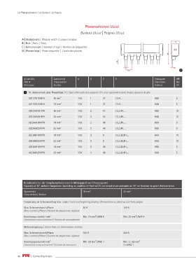
UL Phasenschienen | UL Busbars |  UL Peignes


                                                       Phasenschienen ULcut
                                                    Busbars ULcut | Peignes ULcut

               A | Modulbreite | Module width   |  Larguer module
               B | Pole   | Poles   |  Poles                                                                    22
                                                                                                                22
               C | Fahnenanzahl | Number of lugs  | Nombre de languettes
               D | Phasenfolge | Phase sequence  |  L'ordre des phases
                                                                                                            5858

                                                                            13,8 13,8
                                                                                5 5                            1,8
                                                                                                               1,8
                                                                                  17,6                             1
                                                                                  17,6
                Artikel-Nr.        Querschnitt    A       B       C       D                        Endkappen     VPE
                Part #             Cross section                                                   End covers    Qty
                Référence          Section                                                         Embout        UV

                 1  H1, Abstand nach jeder Phasenfolge | H1, Space after each pole sequence | H1, avec espacement après chaque séquence de pôle
                   ULC137A18H1FA   18 mm²         17,6    1       37      L1,H1,...                A68           5

                   ULC137A25H1FA   25 mm²         17,6    1       37      L1,H1,...                A68           5
                   ULC210A18H1PA   18 mm 2        17,6    2       10      L1,L2,H1,...             A68           10

                   ULC210A25H1PA   25 mm 2        17,6    2       10      L1,L2,H1,...             A68           10
                   ULC246A18H1PA   18 mm 2        17,6    2       46      L1,L2,H1,...             A68           5
                   ULC246A25H1PA   25 mm 2        17,6    2       46      L1,L2,H1,...             A68           5

                   ULC309A18H1PA   18 mm 2        17,6    3       9       L1,L2,L3,H1,...          A68           10
                   ULC309A25H1PA   25 mm 2        17,6    3       9       L1,L2,L3,H1,...          A68           10

                   ULC348A18H1PA   18 mm 2        17,6    3       48      L1,L2,L3,H1,...          A68           5
                   ULC348A25H1PA   25 mm 2        17,6    3       48      L1,L2,L3,H1,...          A68           5


                Belastbarkeit bei 35° Umgebungstemperatur in Abhängigkeit von Einspeisepunkt
                Capacity at 35° ambient temperatur depending on position of feed-in | Á une température ambiante de 35° en fonction du point d’alimentation
                Querschnitt                           18 mm²                   25 mm²
                Cross section | Section

                Einspeisung am Schienenanfang bzw. -ende | Feed-in at beginning /ending | Alimentation au début ou à la fin du peigne

                Max. Schienenstrom Is/Phase           80 A                     100 A
                Max. current Is/Phase | Courant de peigne max. ls/phase


                Anschlussquerschnitt mm 2             Min. 16 mm² | AWG 6      Min. 25 mm² | AWG 4
                Connection cross curent mm  | Section de raccordement
                                  2
                Mitteneinspeisung | Center feed-in | Alimentation centrale
                Max. Schienenstrom Is/Phase           160 A                    200 A
                Max. current Is/Phase | Courant de peigne max. ls/phase
                Anschlussquerschnitt mm²              Min. 50 mm² | AWG 1      Min. 2 x 50 mm²

                Connection cross curent mm² | Section de connexion             2 x AWG 1


            86        |  Connecting Visions
   83   84   85   86   87   88   89   90   91   92   93