
Page 108 - BlueFastening-Systems_Brochure_07192017
P. 108
Flowform® – the innovative sheet metal
Finding the right Flowform®
Selecting the head shape and drive requirements of the application in question. Other designs
can be obtained by arrangement with ARNOLD.
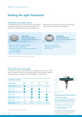
The Flowform® screw comes with two different head variants.
They differ principally in the undercut feature and the drive
geometry. The head geometry is selected according to the
Flat head Truss head
with external drive with internal drive
Factory standard: AWN-02-01-06 Factory standard: AWN-02-01-03
Large underhead feature possible Easier to find the drive
Can accept rising material Smaller underhead recess
Can join several sheet combinations without Economical
pre-drilled hole
Low head height
Other head shapes and drive options available upon request.
Selecting the right screw length
The length of screw necessary depends on the overall thickness of the sheet metals
that are being joined. Because the penetration depth increases during the flow-hole
forming process it is necessary to add in the height of the extrusion-hole.
FLOWFORM® SCREW s3 s1
s2
L
Length L [mm] M3,5 M4 M5 M6 L1
12,00 + 0,8 7,1 mm 8,4 mm 10,4 mm 12,6 mm 1) s3 = s1 + 3 × s2
14,00 + 0,8 2) L = s3 + L1
16,00 + 0,8
20,00 + 0,8 Calculation example
25,00 + 0,8 Desired screw size: M5 clamping part (s1)
30,00 + 0,8 Sheet metal thickness 1.0 mm Screw-in
Dimension: L1 part (s2): Sheet metal thickness 2.0 mm
s3 = 1.0 mm + 3 × 2.0 mm = 7.0 mm
Other dimensions available upon request L = 7.0 mm + 10.4 mm = 17.4 mm
10 108
Selecting the length according
to the list: 20.00 mm
The factor of “3” to achieve the depth of the
extrusion depends on the material and the
joining parameters and may vary.