Page 166 - BlueFastening-Systems_Brochure_07192017
P. 166

POWERLOK® – firm fastening against oscillation and vibration

POWERLOK® – firm fastening
against oscillation and vibration

Screw dimension                                                        Smooth, fully-automated assembly can be achie-
                                                                       ved because there are no malfunctions caused by
POWERLOK® screws comply with quality class 10.9. With                  rolled on fasteners getting hooked up.
slight carbonisation, an even higher surface hardness can              The locking effect is not affected by temperature
additionally be achieved. POWERLOK® screws are a fasten-               or ageing 9as is often the case with chemical
ing and locking device in one. They replace mechanical and             locking methods).
chemical screw lock devices.                                           Feeder malfunctions caused by friction on plastic
                                                                       parts in vibrating feeders cannot occur.

                                                                    Sure and firm fastenings with POWERLOK®
                                                                    screws. They are the right solution for oscillating
                                                                    and vibrating environments!

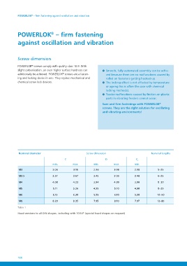
Nominal diameter                 Screw dimension                                              Nominal lengths

                        C                                           D                    C1           5–25
                                                                                        min.         6–25
                  min.     max.                               min.     max.             2.98         8–30
                                                                                        3.48         8–35
M3 3.06 3.16 2.96 3.06                                                                  3.98         10–50
                                                                                        4.98         12–80
M3.5              3.57     3.67                               3.45     3.55             5.98
                                                                                        7.97
M4                4.08     4.23                               3.94     4.09

M5 5.11 5.26 4.95 5.10

M6 6.15 6.30 5.95 6.10

M8 8.20 8.35 7.95 8.10

Table 1
Head versions to all DIN shapes, including with TORX® (special head shapes on request)

08 166
   161   162   163   164   165   166   167   168   169   170   171