
Page 1049 - Med Plaza and Cancer Center
P. 1049
PAGE 16
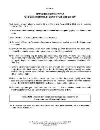
SERVICING INSTRUCTIONS
OHMEDA COMPATIBLE “LATCH-VALVE MECHANISM”
1. Unscrew the two retaining screws (L) until the entire “Latch-Valve Mechanism” can be
removed from the outlet.
2. Remove the four screws (O) holding the connector retaining plate (A) in place. Remove the
plate.
3. Remove the valve body (B) from the valve assembly.
4. Remove the U-spring (N), inspect for wear or damage, reinstall or replace the U-spring as
necessary.
5. Remove the flat washer (I) and valve body O-Ring (J) from the front of the valve body.
Inspect the items for wear or damage and replace the O-Ring seal (J).
6. Remove the retaining ring (F) using appropriate snap ring pliers. Remove the primary cap
(K), primary cap spring (C), primary check valve O-Ring (D), primary check valve (E) and
spring (H). Inspect all items for wear or damage and replace as necessary. Replace the O-
Ring (D).
7. Reinstall all internal components and lock in place with retaining ring (F). Insert the valve
body (B) into the latch valve body. Check that the U-Spring (N), flat washer (I) and valve
body O-Ring (J) are in place. Reinstall the retaining plate (A) and secure with four screws
(O), do not over tighten.
8. Reinstall the “Latch-Valve Mechanism” into the outlet. Coat the valve body (B), with a thin
coat of oxygen compatible silicone lubricant to aid insertion. Tighten down the retaining
screws (L), DO NOT OVER TIGHTEN, as this could damage the Latch-valve.
9. Connect the proper gas specific adapter into the outlet. The connection should be smooth
and the adapter should lock and remain in place allowing gas to flow.
CAUTION: Use caution relative to the type and pressure of
the gas so as not to cause injury.
10. If the assembly does not perform correctly with the adapter installed, replace the entire
“Latch-Valve Mechanism”.
Ohio Medical Corporation ♦ 1111 Lakeside Drive, Gurnee, IL 60031-4099
Medical Gas Outlets—Installation & Maintenance Manual
255084 (Rev.8) 08/2005