Page 551 - Womens Pavilion
P. 551

Corporation


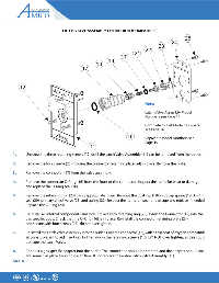
                                    LATCH VALVE ASSEMBLY CHEMETRON (COMPATIBLE)
                                                                                                        25
                                                                                                 24
                                                                                          23
                                                                                  22
                                                                            21
                                                                     20
                                                             19
                                                       18
                                               17


            12


                                 U S E
                                   N O                                            Note:
                                    O  L I
                                                                                  Latch-Valve Assembly Model
                                                                                  Numbers see Page 14

                                                                                  Complete Outlet Model Numbers
                                                                                  see Page 16
                                   #  R O                               16
                                   -  P  O I T A R O  N                           Repair Kit Model Numbers see
                                    )# /
                                                                                  Page 19
                                                   11
        1.     Unscrew the three retaining screws (12) until the Latch Valve Assembly (11) can be removed from the outlet.

        2.     Remove the four screws (25) holding the connector retaining plate (24) in place. Remove the plate.


        3.     Remove the connector (17) from the valve assembly.

        4.     Remove the connector O-Ring (16) from the front of the connector. Inspect the items for wear or damage
               and replace the O-Ring seal (16).


        5.     Remove the retaining ring (23) using appropriate  pliers. Remove the dust cap (18), dust cap spring (19), O-Ring
               seal (20), primary check valve (21) and spring (22). Inspect the items for wear or damage and replace if needed.
               Replace the O-Ring (20).

        6.     Re-install all internal components and lock in place with retaining ring (23). Insert the Connector (17) into the
               gas specifi c body. Check that the O-Ring (16) is in place. Re-install the connector retaining plate (24)
               and secure with four screws (25), do not overtighten.

        7.     Re-install the Latch Valve Assembly into the outlet. Coat the connector (17), with a thin coat of oxygen compatible
               silicone lubricant to aid insertion. Tighten down the retaining screws (12), DO NOT over tighten, as this could
               damage the Latch Valve.

        8.     Connect a gas specifi c adapter into the outlet. The connection should be smooth and the adapter should lock
               and remain in place allowing gas to fl ow. If not replace the entire Latch Valve Assembly (11).
        PAGE   10


                  #                  53 ,)34%$
   546   547   548   549   550   551   552   553   554   555   556