
Page 309 - UK Standard Products Catalogue 2018_23.10.18
P. 309
ANX
Annex
Installation of Flange Plated Lighting Columns.
Installation of Anchor Bolts & Column Levelling.
To ensure that the Anchor Bolts are cast in their correct position they should be held in place using an accurately manufactured
Foundation Template (drawing/sketch on request). It is recommended that the full threaded length of the anchor bolt be left
protruding above the upper surface of the concrete foundation. Prior to casting of the concrete a Cable Duct should be
positioned to enable cables to exit the concrete block centrally under the column flange plate. After the concrete has cured
the foundation template may be discarded or re-used. i.e. dependent upon number of templates used.
Each anchor bolt is supplied with 3 nuts and 2 washers, we recommend that one nut and washer [on each bolt] be
assembled on the underside of the Lighting Column Flange and are used as a means of levelling/plumbing the Lighting
Column. Once the column is positioned and plumbed as required one nut and remaining washer can be tightened to firmly
hold the Lighting Column in place. The final nut is then used as a lock nut.
It is recommended that the gap between the underside of the column flange and the concrete foundation block be filled with
Shrink Proof Grouting Mortar of the same grade as the main concrete mass. A small gap must be left in the grouting mortar
to enable moisture and condensation to escape from the inside of the column base compartment.
After installation the exposed threaded section of the anchor bolts should be protected against corrosion using wax coated
tape [“Denso” tape], or by using grease caps or zinc rich paint.
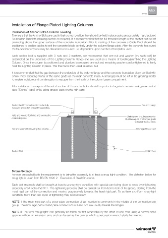
Anchor bolt threaded section to be fully Column Flange
exposed above the concrete foundation.
Nuts and washer for fixing and locking the Shrink proof grouting concrete.
column in place.
Must be equal or stronger grade
to that of the C / Block
Nut and washer for leveling the column. Drainage Hole / Duct
Anchor Bolt Cable Duct
Torque Settings.
For non preloaded bolts the requirement is to bring the assembly to at least a snug tight condition. The definition below for
snug tight is taken from BS EN 1090-2 – Execution of Steel Structures.
Each bolt assembly shall be brought at least to a snug-tight condition, with special care being given to avoid over-tightening
especially short bolts and M12. The tightening process shall be carried out from bolt to bolt of the group, starting from the
most rigid part of the connection and moving progressively towards the least rigid part. To achieve a uniform snug-tight
condition, more than one cycle of tightening may be necessary.
NOTE 1 The most rigid part of a cover plate connection of an I section is commonly in the middle of the connection bolt
group. The most rigid parts of end plate connections of I sections are usually beside the flanges.
NOTE 2 The term “snug-tight” can generally be taken as that achievable by the effort of one man using a normal sized
spanner without an extension arm, and can be set as the point at which a percussion wrench starts hammering.