Page 95 - UK Standard Products Catalogue 2018_23.10.18
P. 95

Aluminium
                                                                                                   Aluminium

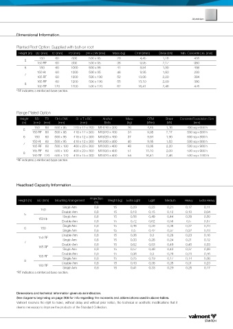
          Dimensional Information


          Planted Root Option: Supplied with bolt-on root
           Height (m)  BD (mm)  TD (mm)  PD (mm)  DH x DW (mm)  Mass (kg)  OTM (kNm)  Shear (kN)  Min. Concrete Dia. (mm)
                     150     60       800     500 x 95       28          4,45       1,16            438
              5
                    150 RF   60       800     500 x 95       36          9,95       2,17            980
              6      150     60      1000     500 x 95       41          9,84       1,90            498
                    150 RF   60      1200     500 x 95       46          9,95       1,83            293
              7
                    165 RF   60      1200     500 x 100      52         13,06       2,20            384
                    165 RF   60      1200     500 x 100      55         13,10       2,09            380
              8
                    180 RF   120     1200     500 x 120      62         16,41       2,46            476
          *RF indicates a reinforced base section.


          Flange Plated Option
           Height  BD   TD   DH x DW    SL x T x BC   Anchor     Mass       OTM       Shear   Concrete Foundation Size
            (m)   (mm)  (mm)   (mm)       (mm)        Bolts       (kg)      (kNm)     (kN)          (mm)
                   150  60   500 x 95  270 x 12 x 200  M14/16 x 300  26     4,45      1,16       400 sq x 600 h
             5
                 150 RF  60  500 x 95  418 x 12 x 300  M18/20 x 400  34     9,95      2,17       500 sq x 800 h
             6     150  60   500 x 95  418 x 12 x 300  M18/20 x 400  37     9,84      1,90       500 sq x 800 h
                 150 RF  60  500 x 95  418 x 12 x 300  M18/20 x 400  40     9,95      1,83       500 sq x 800 h
             7
                 165 RF  60  500 x 100  400 x 20 x 300  M18/20 x 400  48   13,06      2,20       500 sq x 900 h
                 165 RF  60  500 x 100  400 x 20 x 300  M18/20 x 400  51   13,10      2,09       500 sq x 900 h
             8
                 180 RF 120  500 x 120  418 x 15 x 300  M18/20 x 400  54   16,41      2,46       500 sq x 1000 h
          *RF indicates a reinforced base section.


          Headload Capacity Information


                                               Projection
          Height (m)  BD (mm)  Mounting Arrangement     Weight (kg)  Extra Light   Light  Medium  Heavy  Extra Heavy
                                                 (m)
                                 Single Arm      0,8       15       0,29     0,23     0,21      0,17     0,11
                      150
             5                   Double Arm      0,8       15       0,18     0,15     0,12      0,10     0,04
                                                           15
                                                                                      0,44
                                                                                                0,39
                                 Single Arm
                                                                             0,49
                                                                    0,56
                                                                                                         0,30
                                                 0,8
                     150 RF
                                 Double Arm      0,8       15       0,72     0,62     0,56      0,5      0,37
                                 Single Arm      0,8       15       0,46     0,39     0,36      0,32     0,23
             6        150
                                 Single Arm      0,8       15       0,5      0,42     0,37      0,32     0,23
                                 Double Arm      0,8       15       0,36      0,3     0,26      0,23     0,16
                     150 RF
                                 Single Arm      0,8       15       0,33     0,28     0,24      0,21     0,12
             7
                                 Double Arm      0,8       15       0,62     0,53      0,49     0,45     0,33
                     165 RF
                                 Single Arm      0,8       15       0,57     0,48      0,43     0,37     0,26
                                 Double Arm      0,8       15       0,36      0,3      0,26     0,23     0,16
                     165 RF
                                 Single Arm
             8                   Double Arm      0,8       15       0,25     0,19      0,17     0,14     0,08
                                                                             0,38
                                                                                       0,35
                                                                                                         0,23
                                                                                                0,31
                                                           15
                                                                    0,43
                                                 0,8
                     180 RF
                                 Single Arm      0,8       15       0,41     0,33      0,29     0,25     0,17
          *RF indicates a reinforced base section.
          Dimensions and technical information given as an indication.
          See diagrams beginning on page 308 for info regarding the moments and abbreviations used in above tables.
          Valmont reserves the right to make, without delay and without prior notice, the technical or aesthetic modifications that it
          deems necessary to improve the products of the Standard Collection.
   90   91   92   93   94   95   96   97   98   99   100