
Page 2 - Home Exercise Logic Gate_050719_Jawapan
P. 2
1. Logic diagrams are showing the wiring and connections of each individual logic gate that implements the
circuit.
a. Calculate the value of the following Boolean expression.
i. Y = A + C(B’·C), where A = 1, B = 0 and C = 1
[2 marks]
Y = 1 + 1(0’.1)
= 1 + 1(1.1)
= 1 + 1(1)
= 1 + 1
= 1
ii. X= (A+B)’ (B’+C), where A = 1, B = 0 and C = 0
[2 marks]
X = (1+0)’. (0’+0)
= (1)’ . (1+0)
= (0) . (1)
= 0
b. Assume that x=1and y=2. Determine the value of the following Boolean expression and show the
working process.
i. (x=1) AND (y= 3)
[2 marks]
= True AND False
= False = 0
i. NOT ((x=1) AND (y=2))
[2 marks]
NOT ( (True) AND (True) )
NOT ( True )
False = 0
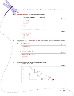
c. Draw logic diagrams for the following Boolean expressions:
i. Q = (X’ + Y) + (Y · Z)’
[4 marks]
X
Y
Q
Z
?
@bm1920