
Page 62 - ISCIR_2017
P. 62
th
APFIS2017 - 6 Asia-Pacific Conference on FRP in Structures
st
Singapore, 19-21 July 2017 3
st
RC slab (1 floor). The construction details of the FRP strengthening were carried out according to fib
Bulletin 14 [4]. A Class 1 ASTM E84 flame and smoke coating was used as fire protection system.
4. Non-destructive structural assessment: In-situ floor load testing
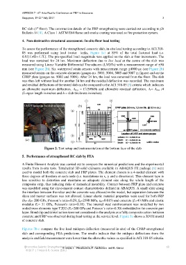
To assess the performance of the strengthened concrete slab, in-situ load testing according to ACI 318-
05 was performed using load (water tanks, Figure 1c) at 85% of the total factored load i.e.
0.85[1.4D+1.7L]. The pre-specified load magnitude was applied on the slab at four increments. The
load was sustained for 24 hrs. Maximum deflection due to live load at the centre of the slab was
measured using Linear Variable Differential Transducers (LVDTs) with a measurement range of ±50
mm (see Figure 2b). Six waterproof strain sensors with measurement range ±4000 (see Figure 2b)
measured strains on the concrete elements (gauges no. 5003, 5004, 5005 and 5007 in figure) and on the
CFRP plate (gauges no. 5002 and 5006). After 24 hrs, the load was removed from the floor. The slab
was then left without load for another 24 hrs and the residual deflection was recorded. The maximum
and residual deflections of the tested slab can be compared to the ACI 318-05 [5] criteria which indicates
2
an allowable maximum deflection, max = L /20000h and allowable residual deflection, r=max /4
(L=span length in inches and h = slab thickness in inches).
LVDT setup at the slab midspan (b)
(a)
Figure 2. Test setup and instrumentation at the bottom face of the slab
5. Performance of strengthened RC slab by FEA
A Finite Element Analysis was carried out to compare the numerical predictions and the experimental
results from in-situ tests. Tetrahedral 3D-solid elements available in ABAQUS FE package [6] were
used to model both the concrete slab and FRP plates. The element chosen is a 4-noded element with
three degrees of freedom at each node (i.e. translations in x, y and z directions). This element type is
less sensitive to distortion and maintains an adequate element size along the whole length of the
composite strip, thus reducing risks of numerical instability. Contact between FRP plate and concrete
was modeled using the slave-master contact characteristics defined in ABAQUS. A small slide along
the interface between the rebar and the concrete was allowed in the model, but separation between the
slave and master surfaces was not allowed. Linear elastic material properties were used for both FRP
(bf= Ef= 200 GPa, Poisson’s ratio=0.29, ffu=2590 MPa, fu=0.015) and concrete (fc=43 MPa and elastic
modulus Ec= 31 GPa, Poisson’s ratio=0.18). The internal steel reinforcement was modelled by two
noded truss elements type T2D2 (Es=200 GPa and Poisson’s ratio=0.30) embedded in the concrete part
layer. Bond slip and dowel action were not considered in the analysis as a fully composite action between
concrete and FRP was observed during load testing at the service level. Figure 3a shows a 3D FE model
of concrete slab.
Figures 3b-c compare the live load midspan deflection (measured in-situ) of the CFRP-strengthened
slab and corresponding FEA predictions. The results indicate that the midspan deflections from the
analysis and field measurement were lower than the allowable values as specified in ACI 318-05 criteria.
oInnovative Seismic Strengthening System for Concrete Structuresp 60
T. Imjai, J. Phumkesorn, P. Ancharoen and R. Garcia
© 2017 | T Imjai & R. Garcia (Eds.)