Page 2 - Discrete Mathematics
P. 2

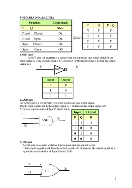
SWITCHES IN PARALLEL:

                           Switches              Light Bulb                     P        Q        P  Q
                      P      Q                       State
                                                                                T        T          T
                     Closed     Closed                On
                                                                                T        F          T
                     Closed     Open                  On
                      Open      Closed                On                        F        T          T
                                                                                F        F          F
                      Open        Open                Off

                   1.NOT-gate
                          A NOT-gate (or inverter) is a circuit with one input and one output signal. If the
                   input signal is 1, the output signal is 0. Conversely, if the input signal is 0, then the output
                   signal is 1.
                                     P             NOT                R


                                            Input        Output
                                              P            R

                                              1             0

                                              0             1
                   2.AND-gate
                   An AND-gate is a circuit with two input signals and one output signal.
                   If both input signals are 1, the output signal is 1. Otherwise the output signal is 0.
                   Symbolic representation & Input/Output Table
                                                                    Input      Output
                     P
                                       AND           R              P    Q        R
                                                                    1     1        1
                       Q                                            1     0        0


                                                                    0     1        0
                                                                    0     0        0

                   3. OR-gate
                       An OR-gate is a circuit with two input signals and one output signal.
                       If both input signals are 0, then the output signal is 0. Otherwise, the output signal  is 1.
                       Symbolic representation & Input/Output Table


                           P
                                                           R

                           Q              OR


                                                                                                         2
   1   2   3   4   5   6   7