
Page 47 - Rail Express - September 2019
P. 47
MODELLING
be located. Mark in acentreline first three screwholes drilled in place with a
and then draw round the fins of the 0.7mm diameter drill to match those in
coupling armmoulding to determine the the cam assembly. The three retaining
minimum sizeofthe opening. screws are‘self-tapped’ into the screw
Using a2mm drillinapin-vice, drill holes to secureeverything.
arow of holes around the inside of the Thecam is tested by moving it to
lines and then push through using a one side and then the other,allowing
modelling knife. File the hole to shape, it to spring back into place. If it is
using the arm moulding to achieve the too slack in the frame, remove the
same curved sided shape as seen on assemblyand pack the oversizearea
the underside of the donor wagons. of the opening with strips of styrene.
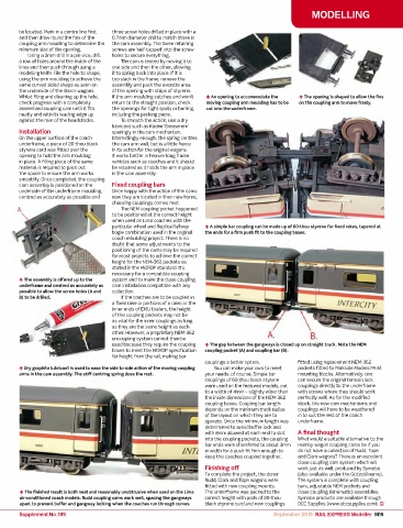
Whilst filing and cleaning up the hole, If thearm moulding catches and won’t ¬ An opening to accommodate the ¬ The opening is shaped to allowthe fins
checkprogress with acompletely return to the straight position, check moving coupling arm moulding has to be on the coupling arm to move freely.
assembled coupling cam untilitfits the openings fortight spots or burring, cut into the underframe.
neatlyand with its leading edgeup including the packing piece.
against the rear of the headstocks. To smooth the action, use adry
lubricant such as Kadee‘Grease-em’
Installation sparinglyinthe cam mechanism.
On theupper surface of the coach Interestinglyenough, the spring centres
underframe, apiece of 20-thou black the cam arm well,but is alittle fierce
styrene cardwas fitted overthe in its action forthe original wagons.
opening to hold the arm moulding It worksbetter in heavier long frame
in place. Afilling pieceofthe same vehicles such as coaches and it should
material is required to pack out be retained as it holds the arm in place
the space to ensurethe arm works in the cam assembly.
smoothly. Once completed, the coupling
camassemblyispositioned on the Fixed coupling bars
underside of the underframe moulding, Once happywith the action of the cams
centredasaccuratelyaspossible and nowtheyare locatedintheir newhome,
choosing couplings comes next.
The NEM coupling pocket happened
to be positioned at the correct height
when used on Lima coaches with the
particular wheel and ReplicaRailway ¬ Asimple bar coupling can be made up of 60-thou styrene forfixedrakes, tapered at
bogie combination used in the original the ends forafirm push fit to the coupling boxes.
coach rebuilding project. Thereisno
doubt that some adjustments to the
positioning of the cams mayberequired
formost projects to achieve the correct
height forthe NEM-362 pockets as
stated in the MOROPstandard. It's
necessary fora compatible coupling
¬ The assemblyisoffered up to the system and to makethe close coupling
underframe and centred as accuratelyas cam installation compatible with any
possible to allowthe screwholes (A and collection.
B) to be drilled. If thecoaches aretobecoupled in
afixedrakeorportions of arake; or the
inner ends of EMU trailers, the height
of the coupling pockets maynot be
as vitalfor the inner couplings as long
as they arethe same height as each
other.However,a proprietary NEM-362
uncoupling system cannot then be
used because theyrequirethe coupling ¬ The gapbetween thegangwaysisclosed up on straight track. Note the NEM
boxestomeet the MOROPspecification coupling pocket (A) and coupling bar (B).
forheight from the rail,makingbar
couplings abetteroption. fittedusing replacement NEM-362
¬ Dry graphite lubricant is used to ease the side to side action of the moving coupling Youcan make your owntomeet pocketsfitted to Parkside Models PA34
arms in the cam assembly. The stiff centring spring does the rest. your needs, of course. Simple bar mounting blocks. Alternatively, one
couplings of 60-thou black styrene cansecurethe original tension lock
were used on the featured models, cut couplingsdirectlytothe underframe
to awidth of 4mm –slightlywider than with screws wheretheyshould work
the inside dimensions of the NEM-362 perfectlywell. As forthe modified
coupling boxes. Coupling bar length stock, the newcam mechanisms and
depends on the minimum track radius couplings will have to be weathered
of thelayout on which theyare to in to suit the rest of the coach
operate. Once the minimum length was underframe.
determined to avoid buffer lock and
with 8mm allowedateachend to slot Afinalthought
into the coupling pockets, the coupling What would asuitable alternativetothe
bar ends were chamferedtoabout 3mm Hornbywagon coupling cams be if you
in width forapush-fit firm enough to do not have acollection of Rudd, Tope
keep the coaches coupled together. andClam wagons?Thereisanexcellent
closecoupling cam system which will
Finishing off work just as well, produced by Symoba
To complete theproject, the donor (alsoavailable underthe Gützold name).
Rudd, Clam and Tope wagons were The system is complete with coupling
fitted with newcouplingmounts. bars,adjustableNEM pockets and
¬ The finished result is both neat and reasonablyunobtrusivewhen used on the Lima The underframe waspackedtothe closecoupling (kinematic) assemblies.
air-conditioned coach models. Rudd coupling cams work well, spacing the gangways correctheight with pads of 20-thou Symoba products areavailable through
apart to prevent buffer and gangway locking when the coaches run through curves. black styrene cardand newcouplings DCCSupplies (www.dccsupplies.com).
Supplement No. 185 September 2019 RAIL EXPRESS Modeller M15