
Page 4 - Microsoft Word - UG Series Operators Manual.docx
P. 4
Basic System Fault Finding
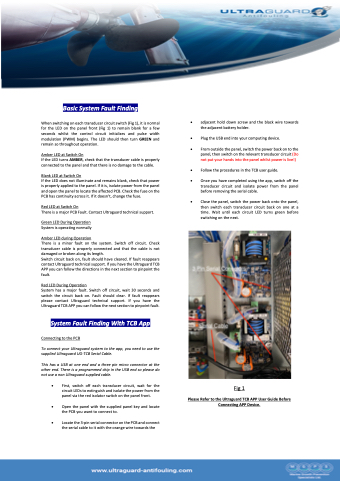
When switching on each transducer circuit switch (Fig 1), it is normal for the LED on the panel front (Fig 1) to remain blank for a few seconds whilst the control circuit initializes and pulse width modulation (PWM) begins. The LED should then turn GREEN and remain so throughout operation.
Amber LED at Switch On
If the LED turns AMBER, check that the transducer cable is properly connected to the panel and that there is no damage to the cable.
Blank LED at Switch On
If the LED does not illuminate and remains blank, check that power is properly applied to the panel. If it is, isolate power from the panel and open the panel to locate the affected PCB. Check the fuse on the PCB has continuity across it. If it doesn’t, change the fuse.
Red LED at Switch On
There is a major PCB Fault. Contact Ultraguard technical support.
Green LED During Operation System is operating normally
Amber LED during Operation
There is a minor fault on the system. Switch off circuit. Check transducer cable is properly connected and that the cable is not damaged or broken along its length.
Switch circuit back on, fault should have cleared. If fault reappears contact Ultraguard technical support. If you have the Ultraguard TCB APP you can follow the directions in the next section to pinpoint the fault.
Red LED During Operation
System has a major fault. Switch off circuit, wait 30 seconds and switch the circuit back on. Fault should clear. If fault reappears please contact Ultraguard technical support. If you have the Ultraguard TCB APP you can follow the next section to pinpoint fault.
System Fault Finding With TCB App
Connecting to the PCB
To connect your Ultraguard system to the app, you need to use the supplied Ultraguard UG-TCB Serial Cable.
This has a USB at one end and a three pin micro connector at the other end. There is a programmed chip in the USB end so please do not use a non Ultraguard supplied cable.
• First, switch off each transducer circuit, wait for the circuit LEDs to extinguish and isolate the power from the panel via the red isolator switch on the panel front.
• Open the panel with the supplied panel key and locate the PCB you want to connect to.
• Locate the 3-pin serial connector on the PCB and connect the serial cable to it with the orange wire towards the
• adjacent hold down screw and the black wire towards the adjacent battery holder.
• Plug the USB end into your computing device.
• From outside the panel, switch the power back on to the panel, then switch on the relevant transducer circuit (Do not put your hands into the panel whilst power is live!)
• Follow the procedures in the TCB user guide.
• Once you have completed using the app, switch off the transducer circuit and isolate power from the panel before removing the serial cable.
• Close the panel, switch the power back onto the panel, then switch each transducer circuit back on one at a time. Wait until each circuit LED turns green before switching on the next.
Fig 1
Please Refer to the Ultraguard TCB APP User Guide Before Connecting APP Device.
